

Introduction
Numerical Model of the Solar House
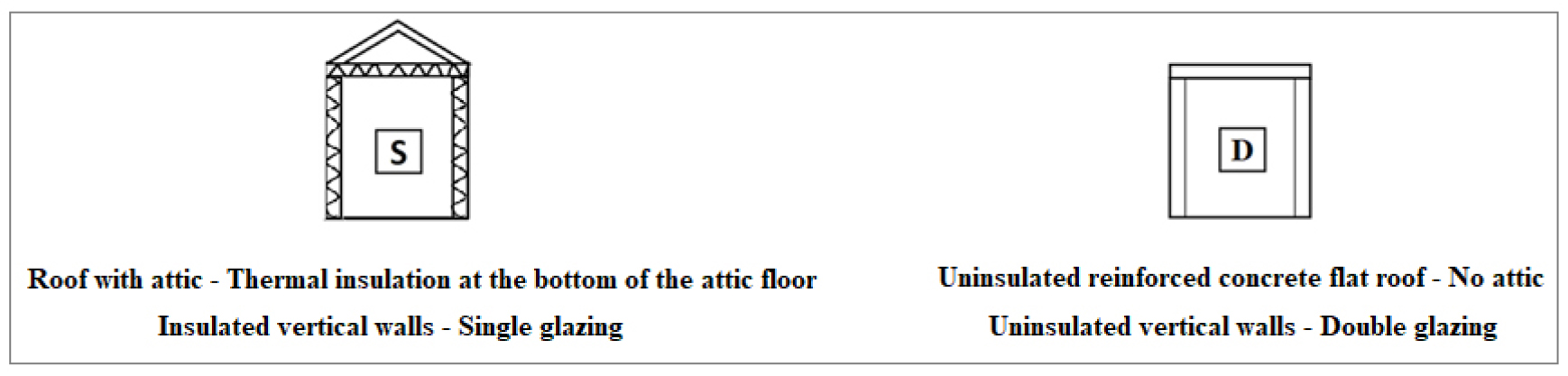
Presentation of the solar house
Experimental setup
Thermal modeling of the ‘solar house’
Analysis of results
Simulations for Different Housing Configurations
Principles adopted
Simulation results for the winter period
Simulation results for the summer period
Influence of the attic ventilation rate on the energy needs of the dwelling
Conclusion
Introduction
Algeria has seen its internal energy consumption increasing significantly passing from 17 million tons of oil equivalent (TOE) in 2005 with 33 million inhabitants to 60 million TOE in 2019 with 43 million inhabitants (source ONS, The National Office for Statistics). The building sector is the largest energy consumer by absorbing 41% of total final energy consumption [1]. This is mainly due to the number of dwellings which has increased significantly in recent years. Thus, according to the Ministry of Housing and Urban Development, the national housing park had 9.6 million inhabitants at the end of 2018 recording an increase of nearly 60% compared to 2004. It should be noted that most of the existing buildings were built without considering their energy efficiency [1]. If this trend is maintained, internal energy consumption by 2040 may double compared to 2019. These figures show that it is urgency to take practical energetic measures in order to inflect the consumption curve, particularly in this sector.
A diagnosis of the residential sector has revealed that the noticed increase in its energy consumption is mainly due to the large use of heating and air conditioning systems [1]. In order to significantly reduce energy needs of a building, its orientation, shape and the thermal insulation of its envelope are the most important variables that should be considered. In fact, the designer’s job is to choose the right building orientation that allows increasing solar gain in winter and mitigating these gains in summer and mid-season [2]. By optimizing the shape and orientation of the building, it is possible to achieve energy savings on the heating load up to 36% [3]. On the other hand, the use of shading can allow realizing up to 20% energy savings for air conditioning [4].
The openings such as windows are considered as an important source of energy losses and are therefore a thermal weak point to strengthen. About 10-20% of heat losses in a building occur through glazing in winter [5]. However, in summer, the glazing let in important calorific intake inputs. The use of low-emissivity double glazing remains the best solution in the summer to minimize solar radiation entering through the south, east and west facing facades and allow to reduce the need for air conditioning [6].
It is to note that the roof is the main source of heat losses and gains in individual buildings, due to its exposure to the wind and its large surface area that is in contact with both the interior and the exterior.
The thermal insulation of the walls significantly improves the feeling of comfort inside the dwellings. A high performance thermal insulation removes the cold wall effect in winter. The effectiveness of thermal insulation depends on the nature and type of the thermal insulation and its thickness [7]. The position of the insulation layer, whether external or internal, has only a low impact on the annual energy consumption of the building [7]. In Algeria, thermal insulation mainly concerns the roof and sometimes the exterior walls. Walls in contact with the ground are rarely thermally insulated [1]. The most commonly used insulating materials in Algeria are expanded cork, expanded polystyrene, glass wool and rock wool.
Discontinuous operation of heating systems and dependent air conditioning, depending on the occupancy of the rooms, can also contribute significantly in reducing the overall consumption of a building [8].
Outside air infiltration, during winter, is an important factor that affects considerably the heating load of buildings. Air infiltration occurs through large openings such as doors and windows, as well as cracks in the exterior walls. The air transfer rate is affected by the temperature differences between the both sides of the building, wind speed (roughness of the site) and the architecture of the building. Outside air infiltration has a great impact on indoor air quality [9].
The present study aims to evaluate the energy performance of an individual house having an attic type roof considering the Algerian climate context.
In Algeria, the attic structure is mainly made using wood or concrete. The roof tiles are made in either terracotta or concrete. Many previous works on attics have been dealing with the study of the ventilation of these spaces, the control of temperatures in summer and the accumulation of moisture during winter [10, 11]. Traditionally, building codes require that the attic of residential buildings be ventilated to avoid damage from excessive moisture [12]. The purpose of attic ventilation is also to evacuate hot air produced in summer as a result of solar gains through the roof [13]. The ventilation system generally consists of an electrically-powered fan that can be connected to photovoltaic panels [14].
The adopted methodology consists of developing a numerical model of an experimental house, called a solar house [15], which is located in the city of Bou Ismail near Algiers within the site of the Solar Equipment Development Unit (UDES). This solar house is representative of typical Algerian individual houses with attic. This numerical model was obtained using the TRNSYS software [16]. The developed numerical model was validated by experimental measurements through comparison of calculated and measured indoor air temperatures. In a second step, the validated numerical model was used to run simulations in order to assess the influence of the attic on the energy needs for different variants of the experimental house.
Numerical Model of the Solar House
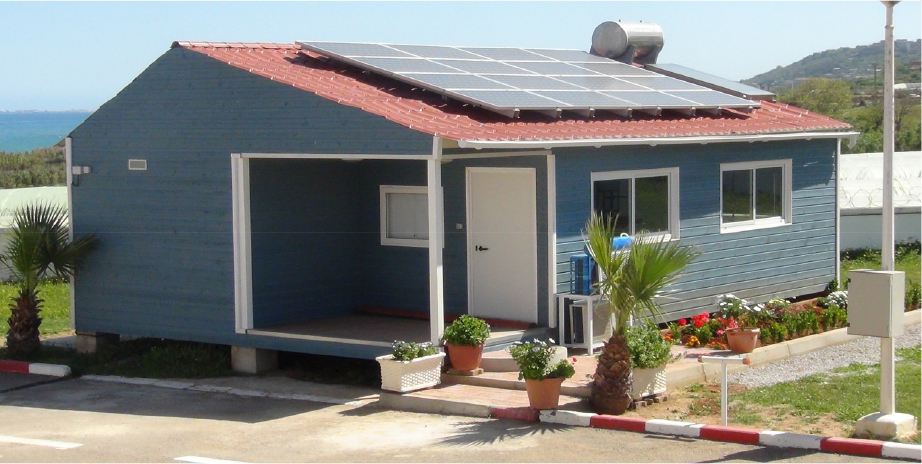
In a first step, the objective is to obtain a validated numerical model of the UDES solar house (see Figure 1). The name “solar house” was adopted in relation to the fact that it is equipped with photovoltaic solar panels installed on the roof ensuring its electrical supply.
Presentation of the solar house
The solar house used as a demonstrator is rectangular in shape and oriented North, South, East and West (see Figure 2).

The roof above the attic is made of galvanized sheet metal. The floor separating the attic from the lower parts is thermally insulated with polyurethane. The vertical walls of the solar house are made of wood and insulated with polyurethane. There is an air gap of about 30 cm between the low wooden floor and the soil.
The interior layout of the solar house is shown in Figure 3.

We considered three thermal zones:
•Zone 1 which is called «cell», it contains a bedroom, a living room, a kitchen and the bathrooms.
•Zone 2 which contains the attic and zone 3 which contains the technical room.
There are horizontal openings between the roof sheeting of the attic and the vertical walls (see Figure 4). These openings cause significant air infiltration at the attic. They were estimated at 60 air changes per hour (ACH) taking into account the average wind speed and the section of the openings.

Experimental setup
The experimental data measured at the ‘solar house’ level are: indoor air temperature, outdoor air temperature, direct and total horizontal solar radiation and wind speed.
For the measurement of indoor air temperatures, K-type thermocouples were used. Temperatures were recorded every five minutes by using a Fluke type data logger having an accuracy of ± 0.1°C.
Six thermocouples were used for our study as follows:
1.three thermocouples were placed in the cell (two thermocouples were placed in the bedroom and one thermocouple was placed in the living room);
2.two thermocouples were placed in the attic (one north side and the other south side);
3.one thermocouple was placed at the technical room.
The thermocouple placed in the living room was wrapped by an aluminum cylinder (see Figure 5) to protect it from sunlight. The thermocouples at the bedroom have not been protected because of absence of any direct solar radiation since the room is oriented North.

The external experimental data were measured using the meteorological and radiometric station(see Figure 6) located at the UDES site. The weather station is equipped with a compact WXT 520 sensor, which measures several meteorological parameters such as temperature of ambient air, humidity, atmospheric pressure, speed and direction of wind. Moreover, the station is provided with two pyranometers to measure solar radiations, one for horizontal solar radiation and the other for solar radiation received on a 36° inclined plane, as well as a tracker to measure diffuse and direct radiations. The station is equipped with a CR1000 data logger, which collects data from the various sensors every 5 minutes. Table 1 provides the characteristics of the used instruments.

Table 1.
Characteristics of meteorological and radiometric instruments
Thermal modeling of the ‘solar house’
TRNSYS software version 14 was used to model the thermal behavior of the solar home. TRNSYS is a software developed by the Solar Energy Laboratory at the University of Madison (USA) [16]. It allows dynamic thermal simulation of buildings and associated systems. TRNSYS has a number of components called TYPES for which an identification number is assigned to each model type. The TRNSYS library contains several families of components to model and simulate a complete building environment. These components include a building, heating equipment, solar panel, piping, control system, etc. Within the TRNSYS environment, the user can create his own model for components that are not available in the library [16]. For the simulations carried out in this study, the following components or types were used:
1.TYPE 56: this component allows to introduce the parameters of the solar house and define it to run the simulations. It is necessary to introduce the number of thermal zones, the orientation of the facades, the composition of the walls, the thermo-physical properties of the different materials, the internal gains, the rate of air infiltration and the mode of the used air conditioning systems (heating, air conditioning and ventilation).
2.TYPE 9: this component enables to use the weather data that are provided by the UDES weather station as input.
3.TYPE 33: this component is used to calculate air characteristics (wet temperature for example).
4.TYPE 16: this component calculates energy intake due to sunlight on a wall (global, direct and diffuse radiation).
5.TYPE 54: this component generates hourly meteorological data from monthly average values using a stochastic calculation model [16].
6.TYPE 25: it retrieves the values of the outputs chosen by the user into a file.
To simulate the operation of a global system, the user must determine which components are present, for what TYPES they correspond to and what relationships exist between them. The simulation is carried out by establishing the connections between the different components as shown in Figure 7.

In order to perform thermal simulations, it is first necessary to identify the thermal zones (or volumes) whose thermal behavior is homogeneous. In general, in the case of housing, it is possible to admit that the air temperatures of the different rooms are very close. Moreover, the floor heights being limited (from 3 to 4 meters), the stratification phenomena are not very pronounced. Thus, three thermal zones were considered (see Figure 3) for this study: the thermal zone 1, called “cell”, contains the living room, the bedroom, the kitchen and the bathroom. This is the habitable part. The temperature values of these different rooms are considered close to each other. The attic constitutes the thermal zone 2 and the technical room the thermal zone 3.
Six orientations were introduced: North, South, East, West, North2 and South2. The North2 orientation corresponds to that of the inclined roof by an angle of 32.4° from the horizontal. The South2 orientation corresponds to that of the inclined roof by an angle of 17° from the horizontal.
The low floor is composed of 22 mm thick wood-based cement-bound panels having a thermal conductivity value of 0.35 W/m.K. The thermal insulation of the exterior walls and the low floor of the attic is ensured by polyurethane panels with a thickness of 40 and 30 mm respectively and a thermal conductivity of 0.028 W/m.K. The thermal conductivity of the galvanized metal sheet (0.75 mm thick) on the attic roof was taken as 51.22 W/m.K [17].
No heating or cooling systems were operated during the test periods. The cell and attic do not contain any internal gain. The technical room contains machines that are running all the time inverters, data acquisition system, microcomputer). In this room, convective inputs were estimated at 167 W and irradiative inputs at 69 W [17, 18].
The openings of the solar house cell (zone 1) (door and windows) remained closed during all test periods. The time chosen for numerical simulations is 1 hour. Air transfers between thermal zones have been neglected because no opening allows communication between the different considered thermal zones. The convection exchange coefficients were taken constant.
Hourly air infiltration rates were estimated from the mean wind speed and opening section: 60 air changes per hour (ACH) for the attic, 1.7 ACH for the technical room, and 0.5 ACH for the cell.
Analysis of results
In order to validate the numerical model, the calculated and measured values of the air temperatures of the three thermal zones were compared. The tests were conducted in winter and summer.
Winter simulations were conducted from December 30, 2019 to January 13, 2020. The results are shown in Figure 8.
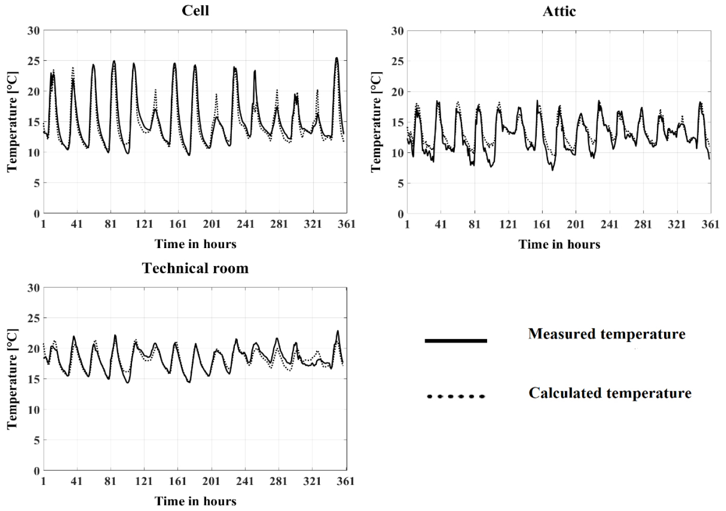
The summer simulations were conducted from August 27 to 30, 2020. The results are shown in Figure 9.

The comparison of experimental and calculated values was made by calculating the Normalized Mean Bias Error (NMBE) and CVRMSE (Coefficient of Variation of the Root Mean Square Error) coefficients by using the following formulas [19, 20]:
In formulas 1 and 2, n represents the number of measurements, m the value of the measured variable (air temperature in this case), s the value of the calculated variable (air temperature) and the mean of the measured variable. Table 2 provides the values of the NMBE and CVRMSE indices obtained for the different thermal zones and the considered periods.
Table 2.
NMBE and CVRMSE coefficients for each thermal zone according to the considered periods (winter, summer)
| Thermal zone 1 | Thermal zone 2 | Thermal zone 3 | ||||
| Period | Winter | Summer | Winter | Summer | Winter | Summer |
| NMBE (%) | 0.96 | -1 | -6.04 | -1,90 | -3.53 | -2,16 |
| CVRMSE (%) | 9.73 | 3,50 | 11.08 | 4,58 | 6.08 | 4,77 |
The obtained NBME values are lower than 10% in absolute value and the CVRMSE values are lower than 30%. It is observed that the obtained NBME and CVRMSE values are in accordance with the standards that are commonly used in the building field [19, 20]. Thus, despite the uncertainties related to the values of material properties, those related to convection exchange coefficients and air infiltration, the numerical model developed for the dwelling gave satisfactory results. According to these results, the numerical model can be considered validated.
Simulations for Different Housing Configurations
Principles adopted
From an architectural point of view, the UDES solar house can be considered as a typical individual single-floor house with an attic similar to those existing in Algeria (Figure 10). The main objective of this study is to determine the influence of the attic on the energy needs for heating and air conditioning energy of this typical individual house. Several simulations were conducted using the validated numerical model that was developed for the UDES solar house.

The idea of using a validated model of a construction similar to the one studied is very common in thermal studies of buildings [21]. The numerical model of the UDES solar house was used by changing the nature and type of the materials as well as the use of different infiltration rates. It is to note that the geometric dimensions, the architectural layout, orientations and values of convection exchange coefficients have been kept unchanged.
It is important to mention that the climatic zones that are considered by the Algerian thermal regulation are as follows [17]:
1.The A climate zone that includes the seashore and sometimes the northern slopes of coastal chains; the reference temperature values for the design of heating and air conditioning installations, for this climate zone, are respectively 6°C and 34°C;
2.The B climate zone that includes the plain behind the sea shore and the valleys between the coastal ranges and the Tell of Atlas; the reference temperature values for the design of heating and air conditioning systems, for this climate zone, are respectively equal to 2°C and 38°C;
3.We distinguish a climatic zone B’ which includes the Chélif valley. Zones B and B’ have similar winter climatic characteristics. For this climate zone, the reference temperature value for the sizing of air conditioning systems is equal to 41°C;
4.The C climate zone that comprises the highlands between the Tellian Atlas and the Saharan Atlas. The reference temperature values for the sizing of heating and air conditioning systems, for this climate zone, are respectively equal to - 4°C and 39.5°C;
5.Climate zone D that includes the Sahara. The reference temperature values for the sizing of heating and air conditioning systems, for this climate zone, are respectively equal to 5°C and 44 to 48°C.
In this paper, only numerical simulation results related to the climatic zones A, C and D that are presented. The city of Algiers was taken as a reference for the climatic zone A, the city of Djelfa as a reference for the climatic zone C and the city of Hassi Messaoud as a reference for the climatic zone D (see Figure 11).

Meteorological data, outdoor air temperature, horizontal global solar radiation, outdoor air humidity and wind speed were obtained using TYPE 54 TRNSYS model which generates hourly data from monthly average data [16]. The Monthly average data that were calculated over a period of 20 years were provided by the National Meteorological Office (ONM).
The calculated energy needs expressed in GJ were used as a comparison criterion between the different variants of housing. The chosen simulation periods range from the 1st of January to the 28th of February for the winter season, and from the 1st of July to 31st of August for summer.
The simulations were conducted by considering that the cell (thermal zone 1) is heated in winter with a temperature set point temperature equal to 21°C and cooled in summer with a temperature set point of 24°C. The other thermal zones are free floating (not heated and not air-conditioned).
The value of the rate of outside air infiltration at the cell was taken to be 0.5 ACH, which is a usual value for constructions with well-adjusted joinery [18]. The infiltration rate at the technical room level was taken equal to 1.7 ACH, a value estimated from the average wind speed and the section of existing openings at the technical room level. The minimum value of the outside air infiltration rate at the attic was taken to be 0.5 ACH.
Simulations were carried out considering the exterior walls thermally insulated from the inside (see Figure 12). The main advantages of such a configuration are ease of achievement and low cost. However, their major disadvantages are reduction of the interior volume and difficulties when dealing with thermal bridges [1]. The incorporated insulating material between the wall and the partition is generally polystyrene foam, semi-rigid mineral wool or expanded polyurethane. In very cold areas (above 600 m altitude, climatic zone C), a vapor barrier should be placed on the internal face of the insulation.

Numerical simulations were carried out considering the case of a non-habitable attic (thermal insulation at the bottom of the attic) on one hand and the case of a habitable attic (thermal insulation at the top of the attic roof) on the other hand.
Concerning the case of non-habitable attics, it can be made just by laying one or more layers of the insulating material on the attic floor. Mineral wool rolls are used. It is possible, also, to use a blown or spread bulk insulator: blowing of glass wool, rock wool, expanded polystyrene beads or chips, etc. Figure 13 illustrates the choice made for the simulations.

For the habitable attics, the simulations were carried out by opting for a dubbing complex (gypsum board on which is glued a layer of insulation) that is screwed or nailed under the rafters. Figure 14 illustrates the choice made for the simulations.

The values of the thermo-physical properties of the used materials were taken from the Algerian regulations [17]. The thermal conductivity of the insulating materials of the exterior walls and the roof was taken equal to 0.04 W/m.K.
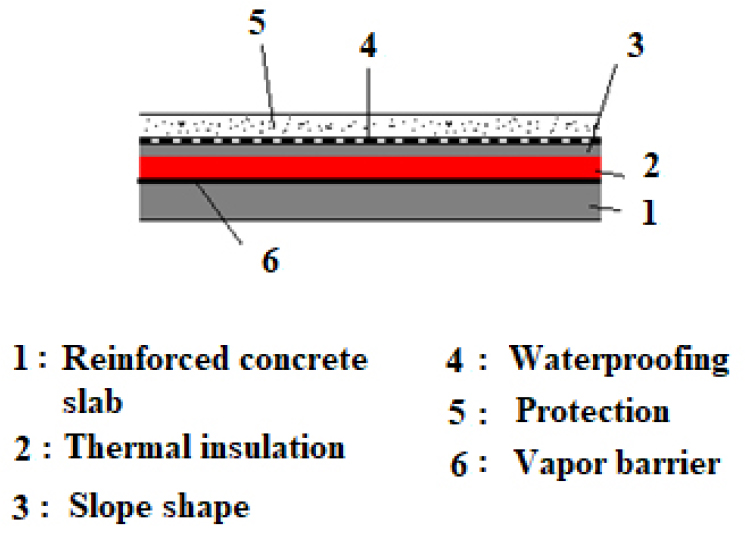
The chosen reference case corresponds to the house with single glazing, without attic, with non-insulated exterior walls, a flat reinforced concrete roof not thermally insulated and a floor in contact with the ground. This configuration resembles that of most individual constructions existing in Algeria. Figure 15 illustrates the thermally insulated roof of the reference house as considered in the numerical simulations.
The different compositions of the walls, as used in the simulations, are summarized in Table 3. In the associated drawings of Table 3, the hatched parts indicate the presence of thermal insulation.
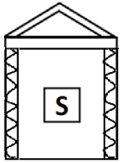
In order to facilitate reading of the simulation results, drawings associated with the different studied configurations were adopted (see Table 3). Two examples of these illustrative drawings are provided in Figure 16.
Table 3.
Walls composition


The floor of the construction is considered to be in contact with the ground and has not been the subject of a specific study. The floor, very often a reinforced concrete slab, is laid on the ground or on gravel and sand. In most cases, it is difficult to isolate such a base. In addition, the inertia due to the ground can be interesting in summer. Therefore, in the Algerian context, the thermal insulation of floors in contact with the ground is not a priority [1].
Simulation results for the winter period
Figure 17 illustrates the energy needs of the cell equipped with single glazing for the studied three sites in case of absence of any thermal insulation of the vertical walls. The value of the external air infiltration rate at the attic level was taken to be 0.5 ACH.

Figure 18 illustrates the energy needs of the cell in the case where the vertical walls have a thermal insulation. The value of the external air infiltration rate at the attic level was taken to be 0.5 ACH.
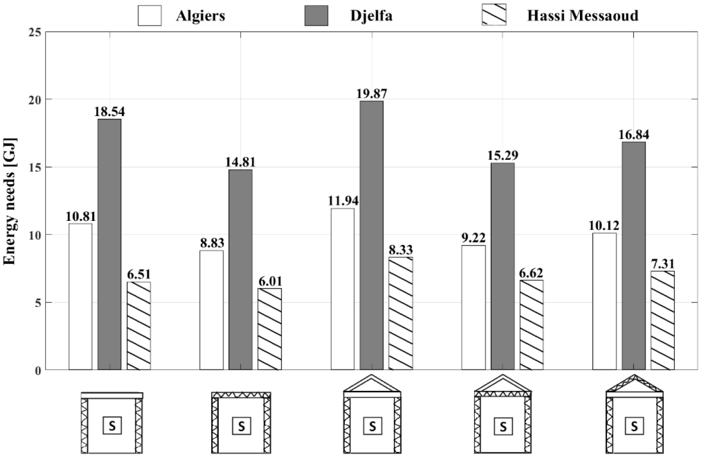
For Algiers and Djelfa, thermal insulation of the flat roof, installation of an attic with bottom or top thermal insulation reduces the energy needs of the cell compared to the reference case located in the same city (see Table 4). On the other hand, when the roof has an attic without thermal insulation, heating energy needs increase slightly (see Table 4). Indeed, in this case, the absence of thermal insulation at the floor of the attic (which is in contact with the cell) allows a significant transfer of heat flux from the cell to the attic.
Concerning the city of Hassi Messaoud, thermal insulation of the flat roof allows a low energy saving (about 7.1%) compared to the reference case. The attic, whether isolated or not, causes an increase in the energy needs for heating the cell (see Table 4). This would be explained by the fact that the roof and the walls of the attic reflect and absorb a significant part of the solar radiation. This energy does not reach the cell and therefore does not contribute to its heating.
Table 4 summarizes the percentage of the decreases and increases in the cell’s energy needs depending on the adopted configuration as compared with the reference cell located in the same city. The sign “-” means a decrease in energy needs.
Table 4.
Decreases and increases in energy needs for different housing configurations compared to the reference case - Sites: Algiers, Djelfa and Hassi Messaoud - Winter period


It should be noted that the cell located in Djelfa (climate zone C [17]) has energy needs for heating more than twice of the energy needs of the same cell located in Hassi Messaoud, and about 60-80% more than the energy needs of the same cell located in Algiers. This is because climate zone C is characterized by a colder winter than the other climate zones.
It is to notice that the thermal insulation of the walls induces a reduction of energy needs that varies between 6 and 10% when the other parameters are kept unchanged.
The results of the simulations show, also, that the installation of a double glazing reduces the energy needs of the cell by nearly 5% for the three studied cities, regardless of the type of the considered envelope.
Simulation results for the summer period
Figure 19 shows the energy needs of the cell where the vertical walls do not have thermal insulation and simple glazing is used. The outside air infiltration rate at the attic was taken to be 0.5 ACH.

Figure 20 illustrates the energy needs of the cell with or without an insulated or non-insulated attic in the case where the vertical walls have a thermal insulation and a single glazing. The value of the outdoor air infiltration rate at the attic level was taken to be 0.5 ACH.

It is observed that during the summer period, the energy needs for air conditioning of the cell decrease appreciably compared to the reference case when thermal insulation is installed on the flat roof or when the roof is equipped with an attic (see Table 5). It is well shown in Table 5 that a non-isolated attic allows energy savings for air conditioning of the cell with the same order of magnitude as a thermally insulated flat roof. The results show, also, that the most interesting case for all cities is a roof with attic and insulation at the bottom (non habitable case).
When the flat roof is insulated or when it is equipped with an attic with no thermal insulation, the installation of double glazing leads to an energy saving in terms of air conditioning needs of about 5.5%. When the roof is equipped with an attic with a thermal insulation, the installation of double glazing allows saving in air conditioning needs of about 8%.
It should be noted that when the cell is located in Hassi Messaoud, the energy needs for air conditioning are 2.5 to 4 times higher than in case the same cell located in Algiers, and 2 to 3 times higher than the case of the cell as located in Djelfa. This is explained by the fact that Hassi Messaoud is located in a desert area characterized by its relatively high temperatures.
Table 5 summarizes the percentage reductions in the cell’s energy needs compared to the reference cell located in the same city.
Table 5.
Decreases in energy needs for different housing configurations compared to the reference case - Sites: Algiers, Djelfa and Hassi Messaoud - Summer period


Influence of the attic ventilation rate on the energy needs of the dwelling
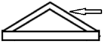
Ventilation of the attic allows reducing temperatures during the summer period on one hand and avoiding the accumulation of moisture during the winter on the other hand. The principle of ventilation of a non habitable attic is schematically illustrated in Figure 21.
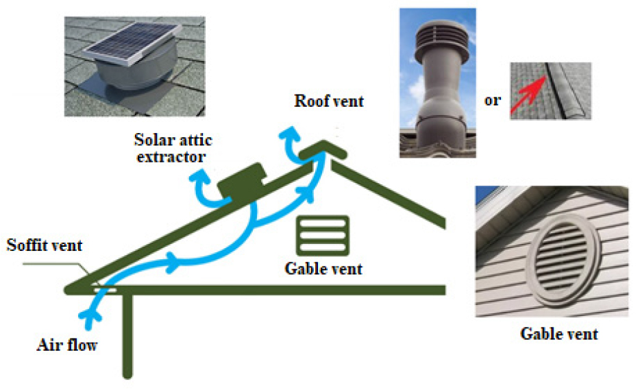
Several types of devices are used to ventilate an attic. They can be natural (without electrical equipment) and consist only of openings (vents) as shown in Figure 21. There are also active devices such as electric extractors which, when provided, must be placed near the highest part of the roof. There are solar attic extractors on the market. These pieces of equipment are composed of an extractor and a photovoltaic panel; so that they can be operated along the day. Their operation can be optimized thanks to a regulation that starts and stops the extractor operation according to a set point temperature.
The influence of the attic ventilation rate on the energy needs of the house was studied by numerical simulation for both winter and summer periods. The ventilation rate was considered along all the day period. The obtained results considering thermally insulated exterior walls in addition to double glazing are presented below. Three types of attics were studied: attic without thermal insulation, attic with thermal insulation of the floor and attic with thermal insulation placed under the roof.
Winter period
The simulation results are shown in Figures 22, 23 and 24.

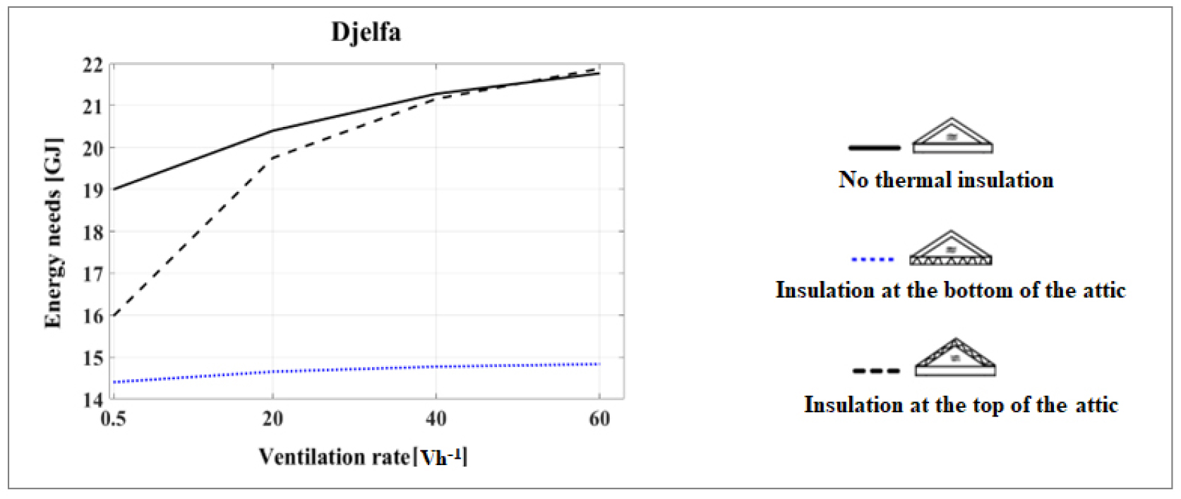

The calculations show that increasing the ventilation rate from 0.5 to 60 ACH at the attic induces a slight impact on the heating energy needs of the cell when the floor of the attic is being insulated. An increase of about 3% in the energy needs of the cell is not worthy for the cell located in Algiers and Djelfa; an increase of almost 6% is remarkable for the cell located in Hassi Messaoud.
When the attic is not thermally insulated, the heating energy needs of the cell increase by almost 15% for the city of Algiers, 13% for the city of Djelfa and 22% for the city of Hassi Messaoud considering an increase in the ventilation rate of the attic from 0.5 to 60 ACH.
When only the roof of the attic that is insulated, the heating energy needs for the cell increase by almost 32% for the city of Algiers, 27% for the city of Djelfa and 35% for the city of Hassi Messaoud if the ventilation rate of the attic is increased from 0,5 to 60 ACH.
For the cell located in Hassi Messaoud, from a ventilation rate of the attic of around 20 ACH, the energy needs of the cell with a thermally insulated attic roof (habitable case) exceed those calculated for the cell with a non isolated attic. In fact, the heat flow resulting from the tiles that are heated by the solar radiation is slowed down by the thermal insulation that is placed under the attic roof. Thus, the attic benefits slightly from solar gains and heat exchanges between the attic and the cell will be more significant, which will induce an increase in the energy needs of the cell.
Summer period
The simulation results are shown in Figures 25, 26 and 27.


When the floor of the attic is insulated and the rate of ventilation is increased, a saving of nearly 9% is remarkable on the energy needs of the cell in Algiers, 7% for the cell in Djelfa, and 2% for the cell at Hassi Messaoud. Starting from a value of the ventilation rate equal to 60 ACH for Algiers, 40 ACH for Djelfa and 20 ACH for Hassi Messaoud, the decrease in the energy needs of the cell becomes negligible.
When the attic has no thermal insulation and if the ventilation rate of the attic is increased from 0.5 to 100 ACH, the energy needs of the cell decrease by almost 20% when it is located in Algiers, 15% when it is located in Djelfa and 2% when it is located in Hassi Messaoud.
When the ceiling of the attic is insulated and the ventilation rate increases from 0.5 to 100 ACH, we note a decrease in the air conditioning needs of the cell by nearly 18% for the cell located in Algiers and 8% for the cell located in Djelfa. For the cell located in Hassi Messaoud, an increase in air conditioning needs of nearly 10% is observed when the ventilation is increased. In fact, in this city, attic ventilation is carried out with outside air at a temperature that is close to 48°C during the day. When the thermal insulation is placed at the top of the attic, the heat stored inside the attic will be difficult to evacuate through the roof and more easily transmitted to the cell, which causes an increase in the cell’s energy needs for air conditioning.
The Tables 6 and 7 provide some recommendations regarding the interest of an attic according to the climatic zone. The installation of an attic is said to be “interesting” if energy savings for heating and air conditioning are possible, in view of the results of this work.
Table 6.
Recommendations for attic ventilation for Algiers and Djelfa (climate zone A and C)
Table 7.
Recommendations for Hassi Messaoud (climate zone D)
At the end of this study, it appears that a configuration offering a compromise for winter and summer in terms of energy savings for all climatic zones is that of a dwelling with an attic with insulation at the top and external walls thermally insulated. To further reduce energy requirements, attic ventilation must be 0.5 ACH year round for climate zone D and in winter for climate zones A and C, while it must be less than 10 ACH in summer for climate zones A and C.
Conclusion
Since the residential sector is the most energy-intensive in Algeria’s national energy balance, it is the first to be targeted for significant reductions in the country’s energy consumption. To achieve this, actions must be taken on the building envelope. This article presents a study designed to assess the energy performance of attic houses in the Algerian climate. To this end, a thermal model of a single-family home was developed in TRNSYS and validated by experimental measurements. It was then used as a tool to run several simulations.
Various configurations were simulated, to assess the influence of insulating materials, glazing type and ventilation modes on the home’s heating and cooling energy requirements. The different variants selected were compared with a reference dwelling, very common in Algeria, featuring simple glazing, non-thermally insulated walls and a flat reinforced concrete roof with no attic or thermal insulation.
The energy requirements of the living area of a typical house were used as criteria for comparing the different variants studied for dwellings located in three regions representative of Algeria’s main climates: the Mediterranean climate in the north (zone A), the semi-arid continental climate (zone C) and the desert climate (zone D). The main findings of this study are as follows:
In winter, for zones A and C, the installation of thermal insulation at the bottom or at the top of the attic reduces the energy requirements of the living area compared to the reference case located in the same region. However, thermal insulation at the bottom of the attic is preferable. For zone D, the attic, whether insulated or not, has a negative impact on the heating energy requirements of the living area compared to the reference case.
For the summer period, air-conditioning energy requirements are significantly lower than in the reference case when the roof is fitted with an attic. An uninsulated attic provides energy savings of the same order of magnitude as a thermally insulated flat roof: around 60% in climatic zones A and C, and 35% in climatic zone D. The most interesting cases for all regions are either a roof with an uninsulated attic, or thermal insulation at the bottom of the attic.
The increase in attic ventilation has no effect during all the year for dwellings located in the zone D and during winter for those located in the zone A and C. However, a minimum ventilation of 0.5 ACH should be provided to avoid dampness and therefore mould. On the other hand, ventilation does have a beneficial effect in summer for zones A and C. For the attic thermally insulated at the top, air-conditioning energy requirements can drop significantly, sometimes by as much as 20% if the attic ventilation rate is 20 ACH.
This work shows that the installation of a attic is an appropriate solution to the summer periods of Algerian climates that go from mid-May to the end of October. Thus, attics, with thermal insulation at the bottom or without thermal insulation, can help reduce the peak consumption in summer.
