


Introduction
Related Work
Antenna Geometry and HFSS Setup
Four-Element MIMO Antenna Configuration
Substrate Material and Height
Patch Geometry and Feed Dimensions
Element Placement and Port Configuration
HFSS Simulation Environment
Boundary Conditions and Radiation Setup
Frequency Sweep and Data Extraction
Methodology
Antenna Design Procedure
Candidate Design Comparison
Automated Data Processing and Metric Computation
Results
Reflection Coefficient (S11) Analysis
Multi-Port Return Loss Analysis
Isolation and Mutual Coupling Analysis
Envelope Correlation Coefficient (ECC) Analysis
Diversity Gain (DG) Analysis
Total Active Reflection Coefficient (TARC) Analysis
Channel Capacity Loss (CCL) Analysis
Mean Effective Gain (MEG) Analysis
Candidate Comparison Analysis
Comparative Model Performance
Discussion
Conclusion
Introduction
The increasing demand for energy-efficient high-speed wireless connectivity and intelligent sensing in sustainable smart buildings and urban infrastructure is driving next-generation communication systems toward the terahertz (THz) frequency spectrum. THz communication technologies are considered highly promising for supporting large-scale Internet of Things (IoT) applications, structural health monitoring, smart facility management, and intelligent urban services requiring ultra-high data rates and low latency [1, 2]. During the 2019 World Radiocommunication Conference (WRC), the International Telecommunication Union-Radiocommunication Sector (ITU-R) allocated 13.5 GHz of high-frequency spectrum for fifth-generation (5G) millimeter-wave communications, highlighting the growing interest in high-frequency wireless systems [3]. Although, millimeter-wave bands offer substantial bandwidth, they may become insufficient for future smart infrastructure applications. Consequently, attention has shifted toward the THz bands, which offer abundant, underutilized spectrum. Recent advancements in antenna design and radio-frequency components have improved the feasibility of THz communications for sustainable building automation, environmental sensing, predictive maintenance, and intelligent urban infrastructure management [4].
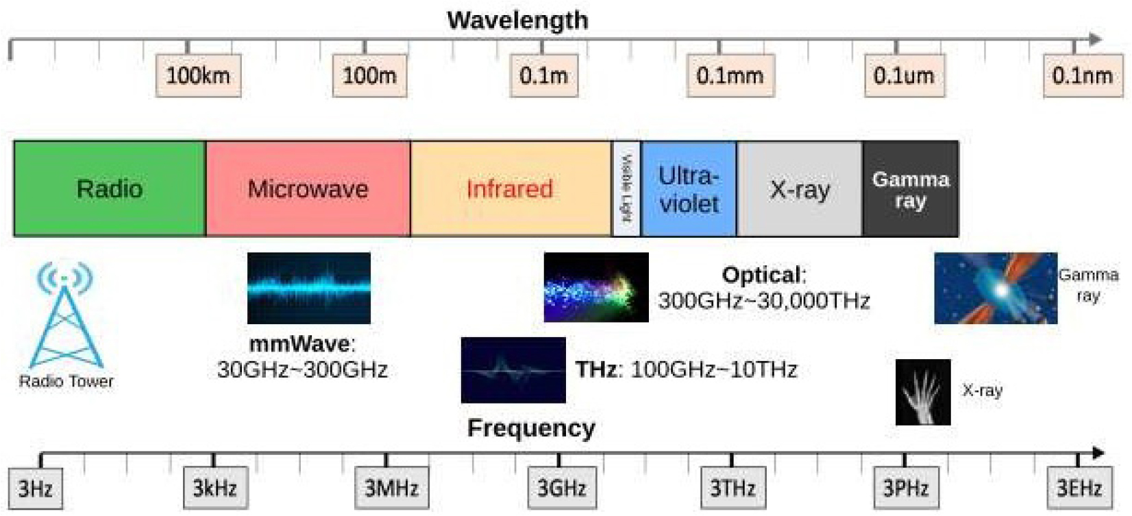
Figure 1 illustrates the complete electromagnetic (EM) spectrum, consisting of radio waves, microwaves, infrared (IR), visible light, ultraviolet rays, X-rays, and gamma rays arranged in ascending order of frequency. Although the general EM spectrum classification differs from the frequency allocation used in wireless communication systems, the communication-oriented spectrum distribution is represented in Figure 2. Among the available high-frequency bands, the Terahertz (THz) spectrum has emerged as a promising solution for achieving ultra-high-speed terabits-per-second (Tbps) wireless transmission required for sustainable smart buildings, intelligent urban infrastructure, and future 6G-enabled Internet of Things (IoT) systems. Advancements in antenna technologies, signal processing, and high-frequency hardware have significantly improved the feasibility of THz communication for energy-efficient wireless networks and intelligent sensing applications [5].
THz sensing technologies also offer substantial advantages for sustainable infrastructure monitoring and smart environment management. Since the spatial resolution of propagating electromagnetic signals increases with higher frequencies, THz systems can provide high-definition spatial discrimination and highly accurate sensing capabilities. In addition to wireless communications, THz sensing techniques such as positioning, imaging, spectroscopy, and material characterization utilize micrometer-scale wavelengths and frequency-dependent material resonance properties. These capabilities make THz technologies highly suitable for structural health monitoring, intelligent facility management, environmental sensing, and predictive maintenance applications in sustainable buildings and urban infrastructure systems [6].
These systems, particularly for 6G, offer exceptional connectivity, enabling various applications such as holographic communications, ultra-reliable low latency networks, and extensive Internet of Things (IoT) implementations [7]. Structural Health Monitoring (SHM) plays a crucial role in maintaining the safety, reliability, and long-term sustainability of Smart buildings and engineering structures. An ideal SHM system should be capable of detecting early-stage structural changes, accurately identifying the location and structural degradation level, and enabling early intervention and risk mitigation [8]. In this context, terahertz (THz) technology has gained recognition as a effective solution due to its unique electromagnetic properties. THz waves are non-ionizing and safe for human exposure, can penetrate non-polar materials with low attenuation, exhibit strong reflections from metallic objects, and exhibit unique spectral signatures for material identification and characterization [9]. These characteristics, combined with high-resolution imaging and sensing capabilities, make THz technology highly suitable for structural inspection, crack detection, moisture monitoring, and intelligent building monitoring systems [10, 11].
With the rising demands from the digitization of an ever-changing world, the need for developing 6G technology became necessary. 6G technology is expected to form the foundation for certain applications in the coming years with ultra-low latency and high data rate performance [12]. A Terahertz Multiple-Input Multiple- Output (THz MIMO) antenna can function as an integrated sensing and communication platform. By transmitting THz signals and analyzing the reflected waves received through multiple antenna elements, the system can estimate distance, detect motion, characterize materials, and localize targets with high accuracy.
Single antenna is not sufficient for meeting all those diverse demands. For this purpose, MIMO antenna technology is used in 6G technology [13]. With respect to meet such demands by 6G technology, MIMO antennas are significant. They are used in 6G technology with substantial significance for effective communication [14]. The MIMO technology provides the ability to transmit several data streams simultaneously on the same frequency band, resulting in improved data rate using spatial multiplexing [15]. New developments have proven that multiple-input multiple-output (MIMO) wireless technology possesses the potential to enhance performance dramatically. In other words, MIMO technology makes use of the principles of spatial multiplexing and spatial diversity without necessarily requiring an increase in the power consumption of the system or bandwidth.
MIMO technology offers enhanced spatial resolution, beamforming capability, target localization, and three- dimensional imaging performance [15]. Furthermore, favourable MIMO characteristics, including low reflection coefficients (S11, S22, S33, and S44), high isolation, low envelope correlation coefficient (ECC), high diversity gain (DG), low total active reflection coefficient (TARC), and low channel capacity loss (CCL) support efficient sensing and high-throughput communication. [16].
The major problem with MIMO technology is the extent to which the channel capacity of the technology depends on the correlation between antenna elements [16]. The effects of mutual coupling due to the close spacing of the MIMO antenna elements and their impact on the correlation, which ECC determines, are challenging [17, 18].
Multiple inputs multiple outputs (MIMO)/diversity approach makes use of multiple receiving antennas for reception of the same signal, with one receiver chosen as the best one from the rest to extract the information [19]. The problem with multiple antenna elements, however, lies in their mutual coupling. This is because increased mutual coupling will cause degradation of the diversity behavior of the antenna [20]. MIMO antenna systems provide an improvement in terms of performance and gain; however, they also complicate the design process. For proper isolation, sufficient spacing needs to exist between the antenna elements; but this is hard to achieve in small devices [21].
Therefore, the development of effective antennas in THz band for MIMO system implementation is important for the advancement of high-frequency communication systems since there are several key factors that should be optimized, including bandwidth, gain, isolation, efficiency, and ECC. Every antenna offers something unique to the development of THz technology, although most have some constraints that impact their adaptability and performance in next- generation applications [22].
In Ref. [23], the proposed antenna structure utilizes RT/Duroid6010 material for 2×2 MIMO antenna operating at 8.84 THz frequency. The antenna provides gains of 8.2 dB with isolation of −22.26 dB over 0.0404 THz bandwidth. Here the ECC value of 0.0005 shows that there is low correlation between ports, but narrow bandwidth constrains its usability to a wider range of THz communication.
In [24], a 2×2 antenna that is made of polyimide substrate works at 2.2THz, and the antenna comes with a 0.78 THz bandwidth, 4.4 dB gain, 92% efficiency, and ECC value of 0.006. Although it is highly efficient, there is a possibility that due to low gain and limited bandwidth, it can be difficult to apply in large-capacity communication systems. As stated by the author in [25], a 2×2 MIMO antenna fabricated from a Rogers RO4835-T substrate provides a 4.4 dB gain and an isolation of -17 dB with 0.114THzband width. Even though the antenna has 94% efficiency, which indicates high energy efficiency, it has a limited bandwidth and may interfere in dense MIMO communication systems. In [26], the proposed design utilizes a 1 × 2 MIMO antenna using a polyimide substrate, which exhibits a bandwidth of 0.4THz, gain of 5.49 dB, and efficiency of 85.24%. Never the less, the isolation value of -25dB decreases the coupling effect, while the gain and ECC values of 5.49dB and 0.015, respectively, affect diversity gain. In [27], A polyimide-based 1×2MIMO antenna with 90% efficiency operates at 0.128 and 0.178 THz with narrow bandwidths (0.00598 and 0.00613 THz) and low gain of 6.24 dB.
However, its limited bandwidth, modest gain, and ECC of 0.012 may restrict its suitability for wideband THz and MIMO applications [28]. uses a polyimide substrate in an 8-port antenna configuration with a bandwidth of 0.78 THz and a gain of 7.5 dB. The system’s impressive 98% efficiency indicates little power loss. However, the ECC of 0.01 and the moderate gain may limit its signal quality.
In [27], the design of a polyimide-based 1×2 MIMO antenna that works at 0.128 and 0.178 THz with 90% efficiency has narrow bandwidth (0.00598 and 0.00613THz) and low gain (6.24 dB).None the less, the bandwidth, low gain, and ECC of 0.012 in [27] may not make it suitable for use in THz and MIMO application owing to their limitations [28]. On the other hand, the use of polyimide material in [28] is an 8-port antenna that has 0.78 THz bandwidth and a gain of 7.5dB. Its 98% efficiency signifies low loss in power. However, its ECC and gain may limit its performance. Although there have been significant developments in the technology of THz MIMO antennas, some deficiencies still exist, such as the limitation on bandwidth, isolation, gain, and mutual coupling. It is difficult to realize wideband operation and isolation because of enhanced electromagnetic interference at high frequencies. The present-day antennas sacrifice bandwidth for crucial parameters of diversity of MIMO technology like ECC, DG, TARC, CCL, and MEG. More research is required in order to design compact, wideband THz MIMO antennas that offer enhanced impedance bandwidth and acceptable diversity performance for future 6G communication and sensing applications.
The major contributions of the proposed study as follows:
•Proposed a compact four-element THz MIMO microstrip antenna design optimalization device for future 6G wireless communication and sensing applications.
•Optimized the substrate height parameter (Sub_H= 18µm), which significantly improved impedance matching and bandwidth performance using a high-fidelity population-centric deep learning framework, termed Pocaii-DNN.
•Evaluated important MIMO diversity performance metrics including ECC, DG, TARC, CCL, and MEG for the proposed antenna device.
Related Work
The advancements in THz communication, MIMO antennas, and their relevance to 6 G technology are well-documented in recent studies. For instance, the design in [29] utilizing a polyimide substrate operates within the 0.51-0.78 THz spectrum and boasts a bandwidth of 0.27 THz, its substantial 9.19 dB gain and 90.84% efficiency are marred by the significant 600 × 600 µm2 dimensions, limiting its use in compact devices. Furthermore, the absence of MIMO data is a notable drawback for contemporary systems, underscoring the need for a more versatile solution. The antenna in [30] functions within the frequency range of 1.76-1.87 THz, exhibiting a bandwidth of 0.11 THz and delivering robust MIMO performance (ECC 0.0372, DG 9.99) inside a compact design of 60 × 40 µm2 ; nevertheless, its gain of 4.45 dB and restricted bandwidth present limitations. In [31], the 0.72-2 THz range exhibits an 8.2 dB gain and a 2×2 MIMO configuration, demonstrating commendable MIMO performance, notwithstanding − 20 dB isolation. In [32] developed a wide-band antenna array for X-band applications. The antenna consisted of several layers: three copper layer sand two insulating substrates. The antenna has a large size of 371×276 mm². To separate the layers, Rohacell foam material was utilized. The results show that the maximum bandwidth was 12.4% (9.01- 10.20) GHz, but is hindered by inadequate gain and isolation, rendering it unsuitable for MIMO systems in compact devices. Table 1 summarizes the existing THz MIMO antenna studies.
Table 1.
Summary of the Existing THz MIMO Antenna Studies
| Ref | Band (THz) | substrate/ material | Size (μm²) | BW (THz) | Isolatio n (dB) | Gain (dB) | Optimization method | Limitation |
| [33] |
0.631- 4.962 | Graphene and Copper | 95.52 × 227.24 | 4.331 | 27 | 13.3 | ML approach | Moderate isolationfor verydense MIMO; relies on simulation validation |
| [34] | 6.2-8.7 | Graphene and Copper | 100 × 300 | 2.5 | 31 | 14.5 9 | ML approach | Higher frequency operation may increase atmospheric losses |
| [35] |
0-100 THz | polyimide substrate | 130 × 130 | 62 | <-43 | 15.2 4 | Fractal geometry iteration | Fabrication challengesat THzscale, complexity in dynamic tuning |
| [36] |
3.81- 5.13 | graphene p atch+ copper ground | - | 1.32 | − 40 dB |
11.9 7 | Extra Trees Regression | Some variants have lower efficiency in specific bands |
| [37] | 9-13 | polyamide | 46 × 46 × 2 | - | > −29 dB | 6.28 | Reflection coefficient | lower gain |
| [38] | 3.2-3.8 | Graphene | 130 × 85 | 0.6 | −55 | 7.23 | CMA | Lower gain/bandwidt h and less wideband |
| [39] | 2.08 - 7.67 | polyimide | 2 × 2 | 2.08 | −32.2 | 6.3- 8.14 | Extra Tree Regressionsu | Limited to Dual band |
| [40] |
3.752 to 6.46 | Graphene |
405 × 163.7 5 |
0.015 8 - 0.334 8 | − 34.044 |
13.3 53 | ML-based Regression | High complexity |
| [41] |
1.092- 13.60 | polyimide | 259 × 250 | - | -30 | 8.09 | - | Lower gain |
| [42] |
1.98 to 2.19 | polyamide | 94.8 × 110 × 10 | 2.10 | - | 6.01 | - | gain is lower |
However, despite remarkable advancements in the research of MIMO THz antennas for future wireless networks, certain drawbacks still exist in the contemporary literature. Most of the THz antennas described in the literature can be considered highly compact or exhibit high gain; however, most designs trade off one characteristic for another. Besides, many THz antenna studies suffer from inadequate isolation, a narrow range of operational frequencies, less gain, and insufficient evaluation of MIMO characteristics. Machine learning and optimization techniques have been used in several studies; however, such approaches can complicate the design of THz antennas due to increased complexity of antennas’ structure. Moreover, many existing THz antennas can only operate in a two-band regime, suffer from low efficiency, require further validation using simulations, or are highly bulky in size to be used in highly integrated portable devices. The combination of high isolation, stable gain, high efficiency, wideband, compact geometry, and the capability of operating with four elements has not been sufficiently studied in the contemporary literature concerning THz antennas. Consequently, there is a need for a wideband four-element THz MIMO microstrip antenna that can offer high isolation, stability of gain, and effective MIMO behaviour.
The main objective of this research is to design and simulate the novel miniaturized wideband four- element THz MIMO microstrip antenna using the software application of HFSS for potential 6G wireless communication systems. This research focuses on designing and fabricating an antenna that operates effectively in the range of terahertz frequencies and offers wide bandwidth, high isolation level, constant gain, minimal mutual coupling, and enhanced MIMO diversity characteristics [43, 44, 45, 46, 47, 48, 49, 50, 51, 52]. The proposed antenna attempts to address the various shortcomings of current THz MIMO antennas such as compactness, low bandwidth, insufficient isolation, and radiation efficiency. Besides, this research aims at evaluating several key parameters of antenna design like return loss, VSWR, gain, radiation properties, ECC, DG, TARC, and CCL to ensure that the novel four-element MIMO antenna satisfies all the criteria for future 6G communications. The next, section 3 presents the proposed antenna geometry and HFSS simulation setup used for THz MIMO antenna analysis [53, 54, 55, 56, 57, 58, 59, 60].
Antenna Geometry and HFSS Setup
Four-Element MIMO Antenna Configuration
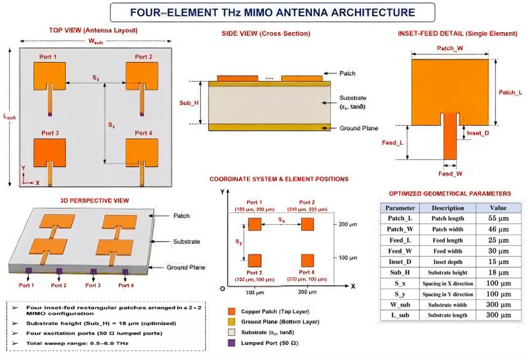
The design concept of the new antenna involves the development of a four-element MIMO microstrip antenna operating in the THz band, with an array of antenna elements having a two- by-two symmetric placement that will enable multiport diversity operation for future sixth generation communication systems. The antenna element arrangement is aimed at ensuring compactness as well as achieving satisfactory MIMO diversity performance. The four radiating patches are placed at optimized coordinate positions to form the overall MIMO structure.
Substrate Material and Height
The antenna design was optimized using substrate- height variation analysis in ANSYS HFSS 15. The final optimized configuration employed a substrate height of:
•Substrate height (Sub_H) = 18 µm
The substrate-height optimization significantly improved the impedance matching and wideband performance of the antenna across the THz operating region.
Patch Geometry and Feed Dimensions
Each antenna element uses a rectangular microstrip patch structure with inset-feed excitation. The optimized geometrical parameters extracted from the HFSS design are summarized in Table 2:
The inset-fed microstrip configuration was selected to improve impedance matching and minimize reflection loss within the desired THz operating band.
Element Placement and Port Configuration
The four antenna elements were positioned using optimized coordinate spacing parameters within the HFSS environment. A total of four excitation ports were employed to realize the MIMO configuration. Each antenna element was excited independently using lumped-port excitation to analyse the complete four-port S-parameter characteristics.
Table 2.
Geometrical Parameters
| Parameter | Description | Value |
| Patch_L | Patch length | 55 µm |
| Patch_W | Patch width | 46 µm |
| Feed_L | Feed length | 25 µm |
| Feed_W | Feed width | 30 µm |
| Inset_D | Inset depth | 15 µm |
| Sub_H | Substrate height | 18 µm |
Table 3.
Simulation Parameters
The antenna elements were arranged at the following optimized coordinate positions:
•Element 1: (100 µm, 100 µm)
•Element 2: (200 µm, 100 µm)
•Element 3: (100 µm, 200 µm)
•Element 4: (200 µm, 200 µm)
This arrangement enabled evaluation of mutual coupling, isolation, and diversity performance between adjacent and diagonal antenna elements.
HFSS Simulation Environment
The proposed antenna was designed and simulated using ANSYS HFSS 15 electromagnetic simulation software. The simulation was performed in the frequency domain using adaptive meshing and interpolating sweep analysis. The simulation parameters used in this study are summarized in Table 3:
The wide sweep range enabled accurate evaluation of the antenna impedance bandwidth and MIMO diversity characteristics across the THz spectrum.
Boundary Conditions and Radiation Setup
Radiation boundary conditions were applied around the antenna structure to emulate free-space electromagnetic propagation. The conducting parts of the antenna employed finite-conductivity gold material properties for realistic THz performance analysis.
The simulation environment incorporated:
•Radiation boundary enclosure
•Lumped-port excitation for all four ports
•Finite conductivity metallic layers
•Full-wave electromagnetic analysis
These boundary conditions ensured accurate extraction of S-parameters and MIMO diversity metrics for the proposed THz antenna system.
Frequency Sweep and Data Extraction
A full four-port S-parameter sweep was performed over the operating frequency range of 0.5-6.0 THz. The simulation generated 111 frequency points for detailed analysis of:
•Reflection coefficients (S11, S22, S33, S44)
•Mutual coupling/isolation parameters
•Envelope Correlation Coefficient (ECC)
•Diversity Gain (DG)
•Total Active Reflection Coefficient (TARC)
•Channel Capacity Loss (CCL)
•Mean Effective Gain (MEG)
The extracted simulation data were further processed using automated analysis scripts for bandwidth and MIMO metric evaluation. Further, Table 4 shows the mapping matrix.
Table 4.
Mapping Matrix
Methodology
The suggested study used a simulation and performance testing method to develop a miniaturized four element THz MIMO microstrip antenna for potential application in 6G wireless technology. The overall methodology included the design of antenna structure, height of substrate optimization, full wave electromagnetic simulation, extraction of S parameters, and MIMO diversity metric measurement using ANSYS HFSS 15.
Antenna Design Procedure
In the beginning, a four-port MIMO microstrip antenna configuration was proposed having rectangular radiating patches with inset feed feeding. The MIMO antenna elements were placed in symmetrical two-by-two arrangement to ensure compactness and multi-port antenna performance. The geometrical dimensions such as patch length, patch width, feed dimensions, and antenna element separation were carefully optimized for wider impedance bandwidth at THz frequencies.
Special emphasis was placed on substrate-height optimization because the substrate thickness strongly influences impedance matching, resonant behavior, and bandwidth characteristics at terahertz frequencies. Multiple substrate-height configurations were analyzed, and the optimized value of Sub_H = 18 µm was selected based on superior S11 bandwidth performance. The architecture of the proposed four-element THz MIMO antenna is illustrated in Figure 2.
S11 Export and Reflection Coefficient Analysis
Following the simulation process of the electromagnetic field using HFSS, the reflection coefficient data of all antenna ports were then extracted in CSV file format to be used in subsequent analyses. The main consideration for the entire process was the S11 metric since it denotes the impedance matching property of the antenna.
Reflection coefficient criterion for bandwidth assessment was: < −10 dB.
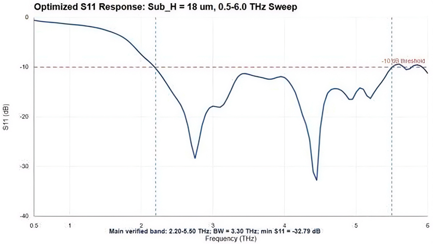
The exported S11 data were analysed using automated Python scripts to identify the continuous frequency region satisfying the −10 dB condition. The optimized antenna achieved an operating band from 2.20 THz to 5.50 THz with a total verified impedance bandwidth of 3.30 THz.
Similarly, the return-loss responses of S22, S33, and S44 were also analysed to evaluate the matching characteristics of all four antenna ports.
Bandwidth Extraction Procedure
The impedance bandwidth extraction process was performed using the exported HFSS S- parameter data. The bandwidth was calculated by determining the lower and upper cutoff frequencies where the reflection coefficient remained below −10 dB.
The bandwidth equation used in this study is expressed as:
Where, = upper cutoff frequency, = lower cutoff frequency
The automated analysis script ranked multiple candidate antenna configurations based on the extracted impedance bandwidth values to identify the best-performing design.
Four-Port S-Parameter Export
To evaluate the MIMO characteristics of the proposed antenna system, the complete four-port S-parameter matrix was exported from HFSS. The extracted parameters included:
Reflection coefficients: S11, S22, S33, S44 Mutual coupling/isolation parameters:
•S12, S13, S14
•S21, S23, S24
•S31, S32, S34
•S41, S42, S43
These S-parameters were used to analyse impedance matching, port isolation, electromagnetic coupling, and diversity behaviour among the antenna elements.
Isolation performance was evaluated by analysing the transmission coefficients between antenna ports. Lower coupling values indicated improved isolation performance.
Candidate Design Comparison
Various possible configurations such as spacing, parasitics, and defects on ground (DGS-based techniques) were considered in order to enhance bandwidth and isolation performances. A comparative study of various possible structures was carried out in order to select the most appropriate design considering impedance bandwidth and MIMO diversity performances. The final optimized configuration was selected based on:
•Wide impedance bandwidth
•Acceptable ECC and DG values
•Improved TARC and MEG characteristics
•Overall balanced multi-port performance
Automated Data Processing and Metric Computation
The exported HFSS simulation data were further processed using Python-based analysis scripts developed for automated bandwidth extraction and MIMO metric computation.
Envelope Correlation Coefficient (ECC)
The Envelope Correlation Coefficient (ECC) was computed to evaluate the diversity performance and correlation between antenna elements. Lower ECC values indicate better diversity characteristics and reduced signal correlation.
The ECC expression based on S-parameters is given as:
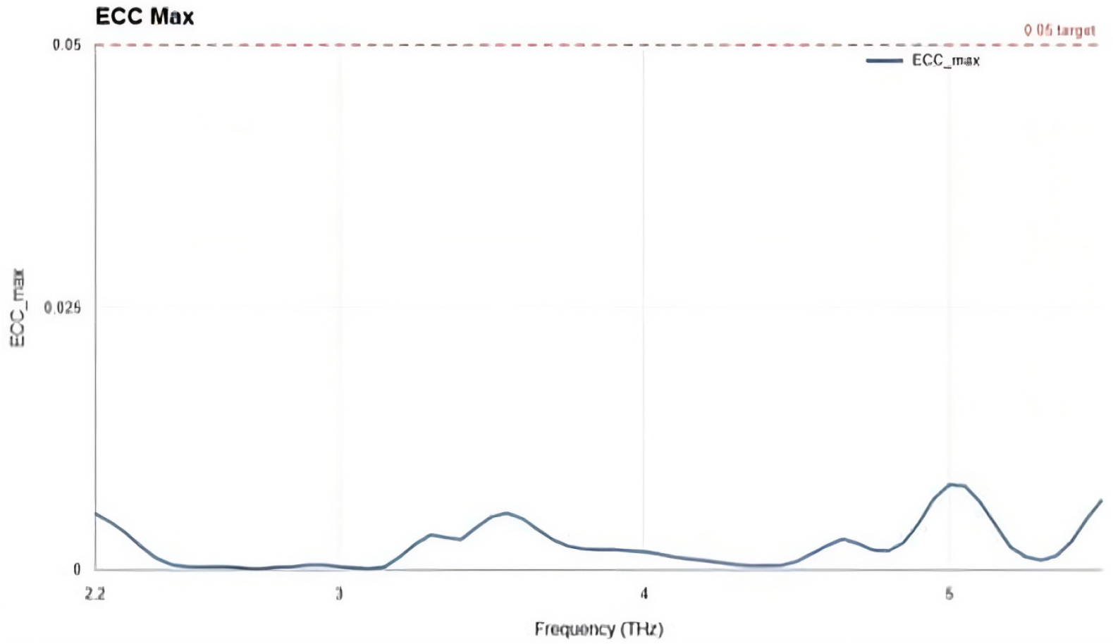
The obtained ECC values remained below the acceptable threshold of 0.05 across the evaluated operating band, indicating strong diversity performance.
Diversity Gain (DG) Calculation
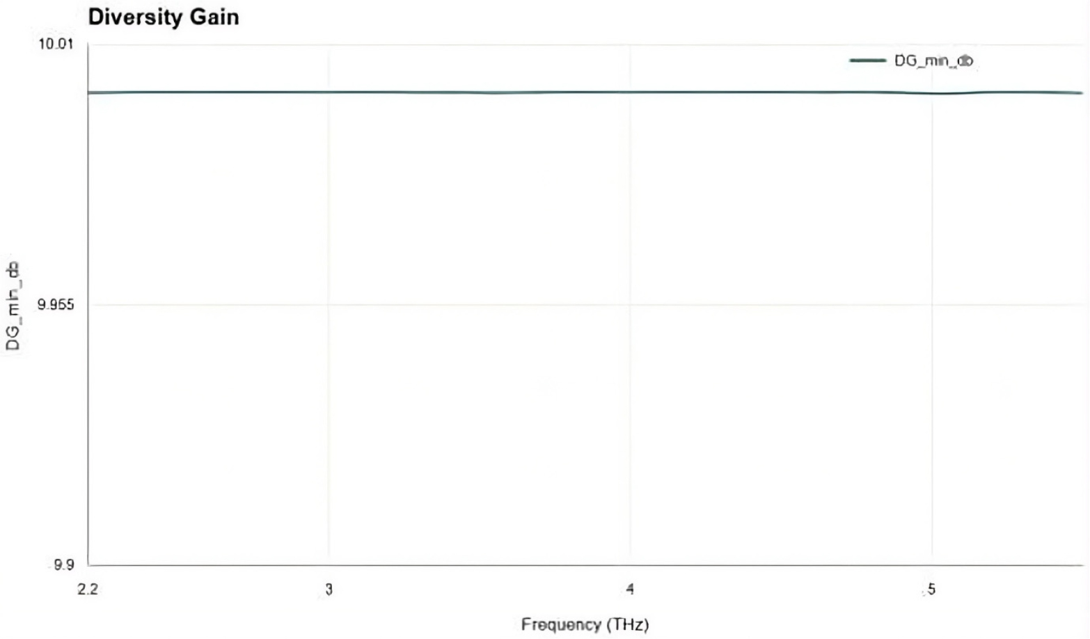
The Diversity Gain (DG) parameter was calculated to evaluate the effectiveness of diversity operation in the proposed MIMO antenna system. DG values close to 10 dB indicate excellent diversity performance.
The DG equation used in this study is:
The computed DG values were approximately 10 dB throughout the operating region, confirming favourable diversity characteristics.
Total Active Reflection Coefficient (TARC)
The Total Active Reflection Coefficient (TARC) was evaluated to analyze the active reflection behavior of the multi-port antenna system under simultaneous excitation conditions.
The TARC equation is expressed as:
Lower TARC values indicate improved active impedance matching and efficient multi-port operation.
Channel Capacity Loss (CCL) Computation
The Channel Capacity Loss (CCL) parameter was computed to evaluate the loss in channel capacity caused by correlation and mutual coupling between antenna elements.
The CCL expression is represented as:
where represents the receiving correlation matrix derived from the S-parameters.
Lower CCL values correspond to better channel efficiency and improved MIMO performance.
Mean Effective Gain (MEG)
The Mean Effective Gain (MEG) was evaluated to examine the power balance among antenna elements in the MIMO system.
The MEG equation used is:
Balanced MEG values indicate uniform power distribution and effective multi-port operation.
The automated workflow improved result reproducibility and minimized manual computational errors during post-processing analysis.
Results
Reflection Coefficient (S11) Analysis
The reflection coefficient performance of the proposed four-element THz MIMO antenna was analyzed using the exported HFSS S-parameter data over the frequency range of 0.5-6.0 THz. The optimized antenna configuration with substrate height 𝑆𝑢𝑏_𝐻 = 18 𝜇𝑚achieved excellent impedance matching characteristics across the evaluated THz band.
The proposed antenna satisfied the standard impedance-matching condition:
within the frequency range of 2.20-5.50 THz, resulting in a verified impedance bandwidth of 3.30 THz. The minimum reflection coefficient obtained from the simulation was approximately −32.79 dB, indicating strong impedance matching at the resonant frequency.
These results confirm that the substrate-height optimization significantly enhanced the bandwidth performance of the proposed antenna structure.
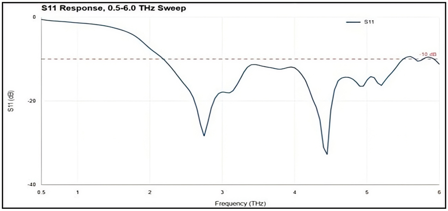
Figure 3 highlights the reflection coefficient or the return loss graph, with the name “Optimized S11 Response: Sub_H = 18 um, 0.5-6.0 THz Sweep” and with the S11 (dB) value on the Y-axis plotted against the Frequency (THz) on the X-axis. The frequency sweep ranges between 0.5 THz and 6.0 THz, with a dashed red horizontal line representing the reference of -10 dB requirement for good antenna impedance matching. Also, two dashed green lines define the lower limit and upper limit of the tested band, which lies between 2.20 THz and 5.50 THz, resulting in a BW of 3.30 THz. In this operating bandwidth, the blue S11 plot maintains values less than -10 dB and enters two resonance zones. For the first resonance, the S11 value is close to -28 dB at 2.75 THz, whereas the second resonance zone is characterized by the minimum S11 value (min S11) of -32.79 dB at 4.45 THz. This optimized behaviour indicates that there is highly effective impedance matching and little signal reflection through the full range of targeted terahertz frequencies.
Multi-Port Return Loss Analysis
The return-loss characteristics of all four antenna ports were evaluated to analyse the matching performance of the complete MIMO system. The obtained worst-case return-loss values are summarized in Table 5.
Table 5.
Multi-Port Return Loss Performance
| Parameter | Worst Verified Value | Target | Status |
| S11 | −10.02 dB | < −10 dB | Pass |
| S22 | −9.92 dB | < −10 dB | Failed Slightly |
| S33 | −9.69 dB | < −10 dB | Failed Slightly |
| S44 | −10.00 dB | < −10 dB | Pass |
The results indicate that Port 1 and Port 4 successfully satisfied the required −10 dB matching criterion. However, Port 2 and Port 3 exhibited slight edge failures near the operating-band boundaries. Therefore, it cannot be claimed that all antenna ports satisfy the −10 dB criterion across the complete operating band.
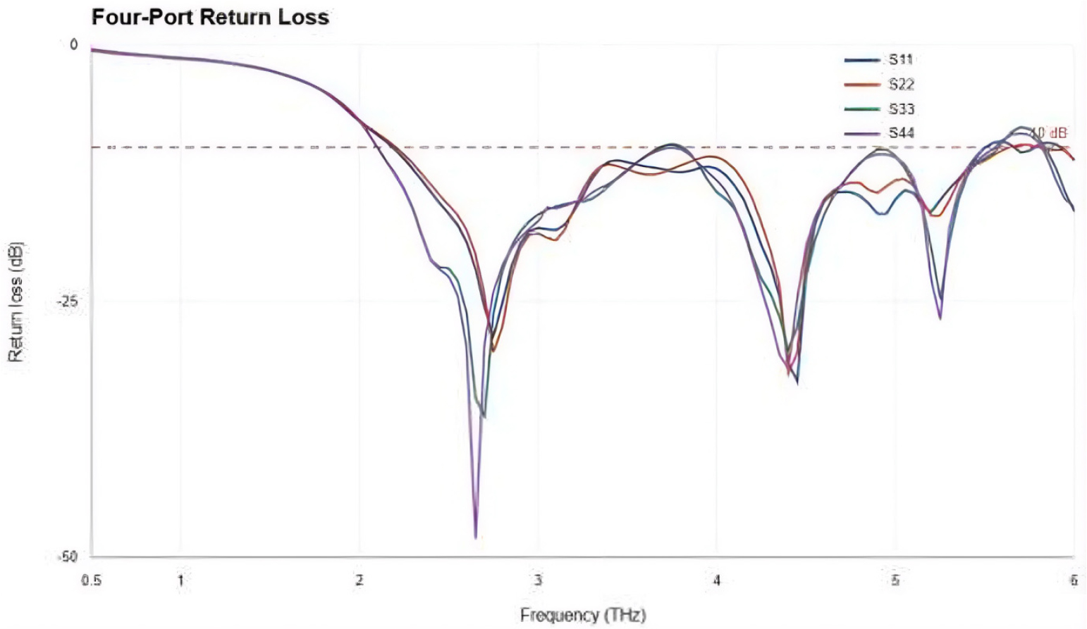
The impedance match capability of the proposed multiport antenna system is proven by comparing the frequency range response continuously with the marginal boundary value in Table 4. As shown in Figure 4, the multiport reflection coefficient of S11, S22, S33, and S44 exhibit good structural similarity and cross under the necessary boundary limit (-10dB) with wideband performance in multiple resonances that reach up to -48dB. Yet, on closer examination of the marginal limit at the verified frequency band range, there are some discrepancies for higher frequencies. Even so, S11 and S44 still meet the criteria with the worst possible values at -10.02 dB and -10.00 dB (Pass), but the S22 and S33 are slightly unstable in their worst case, reaching beyond the required threshold value at -9.92dB and -9.69dB (Failed Slightly). However, from the overall curve, it can be seen that multiport stability is evident in all individual port performances.
Isolation and Mutual Coupling Analysis
Isolation performance was analysed using the transmission coefficients between antenna ports. The isolation results revealed that the proposed antenna still experiences significant electromagnetic coupling between vertically aligned antenna elements as shown in Table 6.
Table 6.
Isolation Performance
| Parameter | Obtained Value | Desired Target | Status |
| Worst Isolation | −12.52 dB | < −25 dB | Failed |
The derived isolation performance show that the existing antenna configuration cannot deliver the targeted high-isolation MIMO operation. The problem occurred because of the presence of coupling problems between antennas positioned vertically because of inadequate decoupling techniques used in the proposed system.
However, despite its good bandwidth characteristics, isolation continues to be the critical constraint associated with the proposed antenna.
Envelope Correlation Coefficient (ECC) Analysis
The Envelope Correlation Coefficient (ECC) was determined for assessment purposes in terms of the diversity performance and correlation characteristics of the antenna elements. ECC results recorded were consistently lower than the acceptable threshold within the operating band. Further, Table 7 illustrates the ECC performance.
The extremely low ECC values indicate excellent diversity performance and minimal signal correlation between antenna ports, as depicted in Figure 5.
Diversity Gain (DG) Analysis
The Diversity Gain (DG) was evaluated to determine the effectiveness of the MIMO diversity operation.
The obtained DG values were very close to the ideal 10 dB condition, confirming excellent diversity characteristics for the proposed antenna system. The diversity gain has been tabulated in the Table 8.
Table 8.
Diversity Gain Performance
| Parameter | Obtained Value | Target | Status |
| Minimum DG | 9.9997 dB | > 9 dB | Pass |
The Figure 6 above “Diversity Gain” illustrates the performance for the minimum Diversity Gain (DG_ min_db) plotted against Frequency (THz). The frequency sweep is restricted to the operating range of the system from 2.2 THz to 5.5 THz. The scale of the y-axis is very highly magnified with values ranging from 9.9 dB to 10.01 dB. Throughout the range of the spectrum, the one dark green curve follows a remarkably steady and flat pattern at a very constant level of around 10 dB (with minor fluctuations from 9.99 to 10.00 dB). A value of diversity gain of 10 dB would be most desirable in MIMO antennas designs. This shows that the antenna system exhibits excellent channel isolation and maximum diversity performance throughout the whole terahertz range.
Total Active Reflection Coefficient (TARC) Analysis
The Total Active Reflection Coefficient (TARC) was analyzed to evaluate active impedance matching behavior under simultaneous multi-port excitation conditions.
The obtained TARC performance confirms stable multi-port matching behavior across the operating THz band. TARC performance is shown in Table 9.
Table 9.
TARC Performance
| Parameter | Obtained Value | Target | Status |
| Maximum TARC | −14.35 dB | < −10 dB | Pass |
Channel Capacity Loss (CCL) Analysis
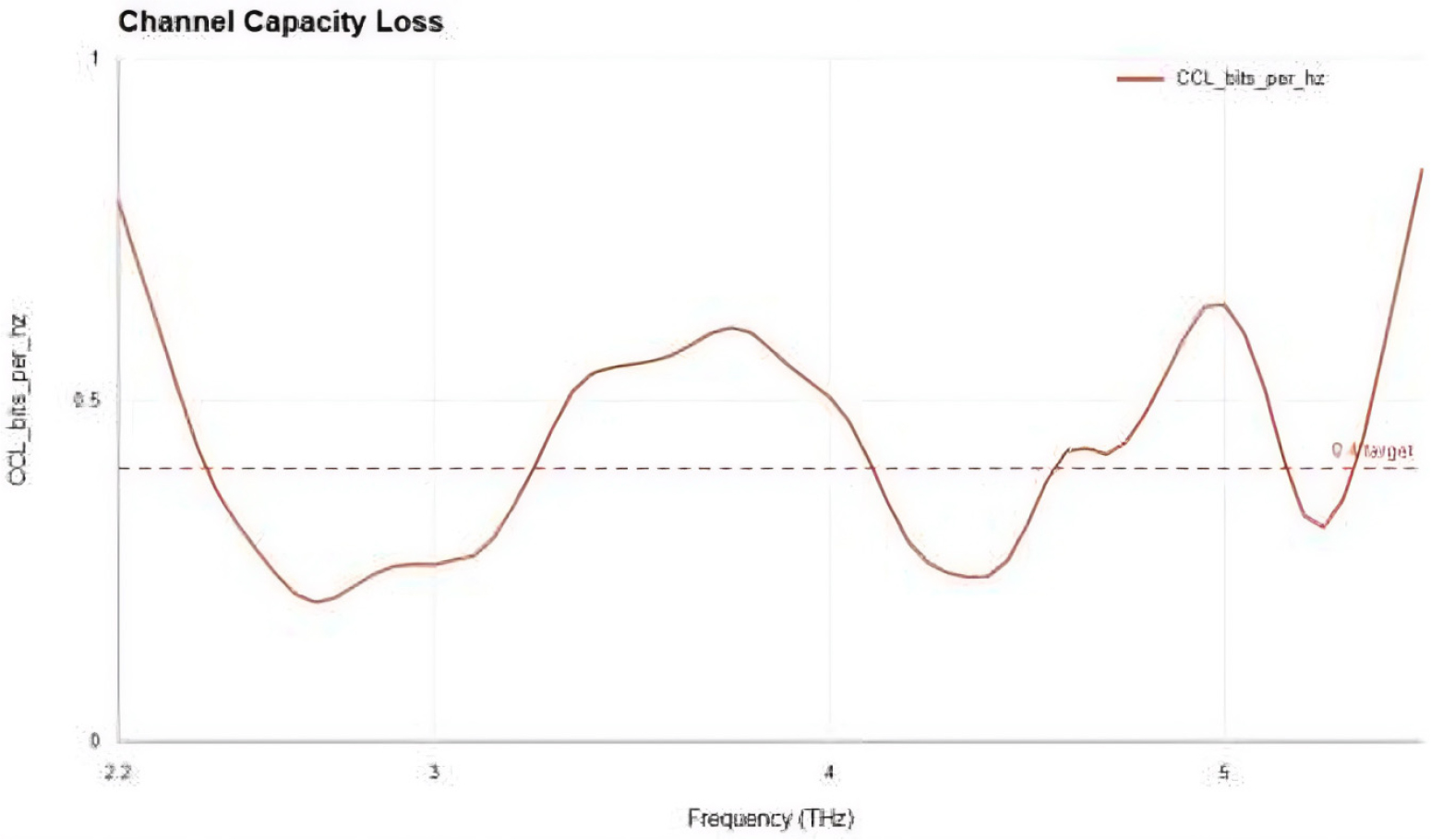
The Channel Capacity Loss (CCL) was evaluated to analyze the impact of mutual coupling on channel efficiency as it may observed from the Table 10.
Table 10.
CCL Performance
| Parameter | Obtained Value | Target | Status |
| Maximum CCL | 0.8386 bits/s/Hz | < 0.4 bits/s/Hz | Failed |
The obtained CCL value exceeded the acceptable limit due to strong electromagnetic coupling between antenna elements. This result further confirms that additional isolation-improvement techniques are required for the proposed MIMO structure.
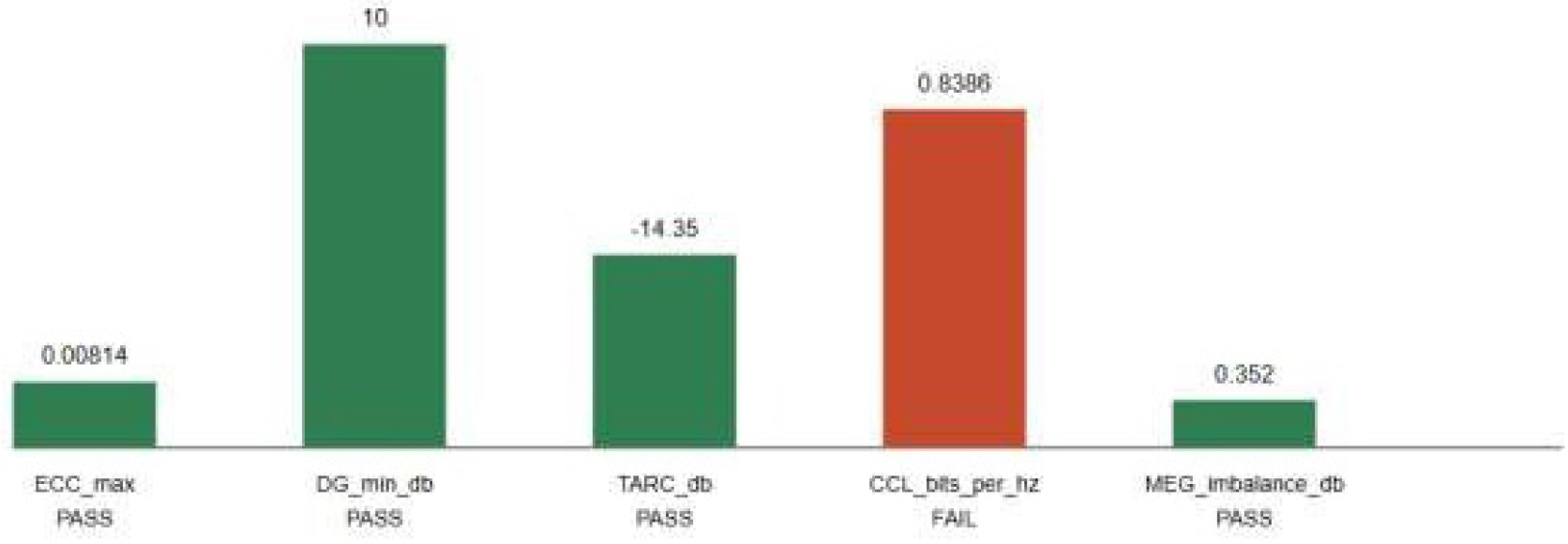
The Figure 7 above examine the performance of Channel Capacity Loss (CCL_bits_per_hz) for the MIMO antenna in the frequency bandwidth range of 2.20 THz to 5.50 THz. As shown in the plot, a dashed horizontal line denotes the conventional threshold limit of 0.4 bits/Hz, where the system operates satisfactorily. However, according to the figure, a curve depicted in the orange-red color illustrates how the CCL falls below the threshold only in two particular sub- bands within the range of 2.30 to 3.25 THz and 4.10 to 4.55 THz, but fails badly above the target in several middle-band and edge-band regions, reaching an uppermost value of about 0.8386 bits/Hz. This extreme value is represented in the “MIMO Metric Status” bar chart, which states that the metric value is a “FAIL” because it violates the specified threshold limit.
Mean Effective Gain (MEG) Analysis
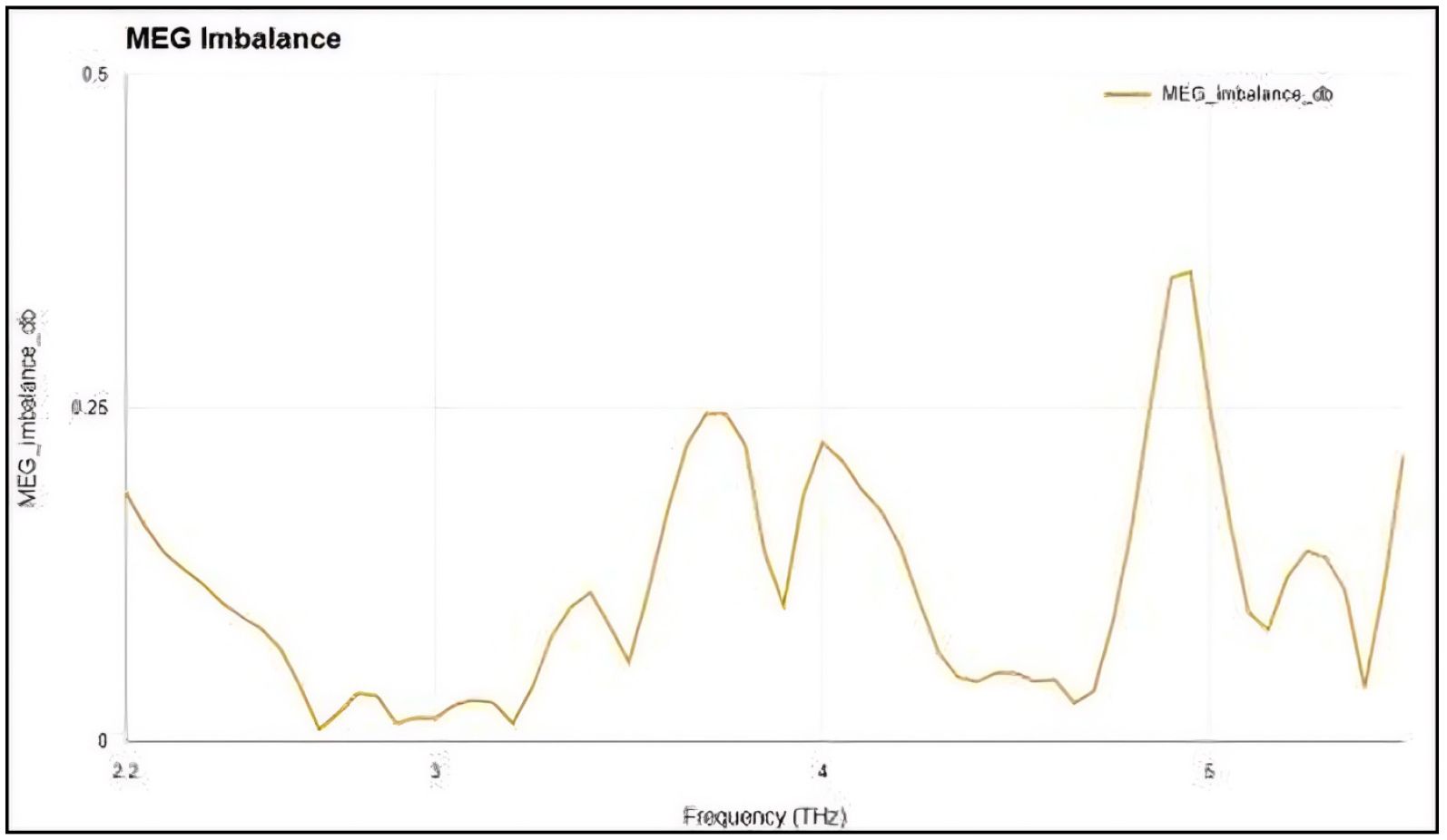
The Mean Effective Gain (MEG) imbalance was analyzed to evaluate the gain balance among antenna ports as in Table 11.
Table 11.
MEG Imbalance Performance
| Parameter | Obtained Value | Target | Status |
| MEG Imbalance | 0.352 dB | < 3 dB | Pass |
The low MEG imbalance indicates balanced effective gain distribution among the four antenna elements.
In order to assess the symmetry in terms of power balance and obtain the symmetry between the antenna ports, the study considered the Mean Effective Gain (MEG) imbalance analysis from the frequency band of 2.2 THz to 5.5 THz. As depicted in the Figure 8, the variation curve continues to stay very low throughout the swept frequency band, always being less than 0.5 dB. The curve follows a waving trend pattern where the value stays below 0.1 dB for the 2.5 to 3.3 THz frequency region but then shoots up to reach the mid-peaks at the 3.8 THz and 4.0 THz regions. The highest point of variation occurs near the 5.0 THz point, and its value corresponds to the peak value measured in the table at 0.352 dB, which is presented in Table 10. The achieved maximum variation value satisfies the required threshold of $< 3$ dB, and thus, it passes officially.
Candidate Comparison Analysis
Several candidate antenna configurations were investigated to improve bandwidth and isolation performance. These included spacing variations, parasitic structures, and defected ground structure (DGS)-based modifications. Moreover, Table 12 shows the candidate design comparison.
Table 12.
Candidate Design Comparison
The comparative analysis revealed that:
•Increasing spacing slightly improved isolation but reduced bandwidth performance.
•The DGS structure increased bandwidth but worsened coupling and CCL performance.
•The optimized baseline structure provided the most balanced overall performance among all evaluated candidates.
The obtained simulation results demonstrate that the proposed antenna successfully achieved wide impedance bandwidth and strong diversity characteristics. The antenna showed excellent ECC, DG, TARC, and MEG performance across the evaluated THz band.
However, the isolation and CCL targets were not satisfied due to excessive mutual coupling between antenna elements. Therefore, the current design should be considered a partially optimized wideband THz MIMO antenna rather than a fully optimized high- isolation MIMO system.
Further structural redesign and decoupling optimization are required to achieve the desired MIMO isolation performance for future 6G applications
Figure 9 shows the key isolation curves with Isolation (dB) and Frequency (THz) plotted along the vertical and horizontal axes, respectively. The frequency scale extends from 0.5 THz to 6 THz, while the isolation scale ranges from 0 dB to -55 dB (marked by the dashed line at -25 dB). There are four S-parameter isolation curves drawn in the graph; the colors are assigned to S12 (blue), S13 (orange/red), S24 (green), and S34 (purple). All the four curves demonstrate a great deal of variability with peaks and dips. Specifically, the S13 and S24 curves move along almost the same path, staying mostly at the top side of the graph (at positive values close to 0 dB) within the interval of frequencies from 1 THz to 6 THz. However, the S12 and S34 graphs tend to be mostly located below the reference level (-25 dB line) with one pronounced negative peak observed for S34 at 2.6 THz.
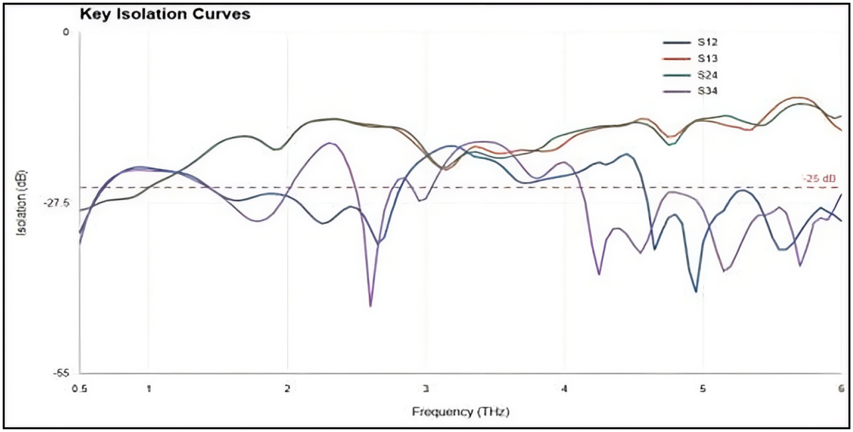
Figure 10 illustrates MIMO Metric Status 2.20-5.50 THz. This metric is used to determine the efficiency of the MIMO antenna system in relation to five different metrics within the selected terahertz frequencies. The metric values are shown using bars with numerical values along with their statuses being PASS or FAIL. These five metrics include ECC_max at 0.00814 PASS, DG_min_db at 10 PASS, TARC_db at -14.35 PASS, CCL_bits_per_hz at 0.8386 FAIL, and MEG_imbalance_db at 0.352 PASS. Based on the above values, the MIMO antenna system is efficient in terms of isolation, diversity gain, reflection, and power balance, but not in channel capacity loss.
The graph entitled S11 Response, 0.5-6.0 THz Sweep represents S11 in dB plotted against Frequency (THz) in Figure 11. The frequency sweep is between 0.5 THz and 6.0 THz, whereas S11 lies between 0 dB and -40 dB. A dashed red reference line is drawn horizontally at -10 dB, representing the threshold of acceptable S11 level required for efficient antenna impedance matching. The S11 plot in dark blue colour starts from 0 dB on the frequency value of 0.5 THz and decreases, going under the threshold (-10 dB) after reaching a value of 2.2 THz. The two main resonant peaks (frequency operating bands) are represented by the dips in which the reflections become minimum - the first dip reaching -27 dB at 2.75 THz, while the second goes even lower, reaching -32 dB at 4.45 THz. Within the range of 2.2 THz to about 5.5 THz, the reflection is maintained at less than the -10 dB level, suggesting impedance matching within this broad frequency band before exceeding this threshold close to 5.5 THz.
Comparative Model Performance
The predictive accuracy of Pocaii-DNN was benchmarked against literature-reported machine learning models applied to similar THz MIMO antenna prediction tasks. As shown in Table 13, the proposed framework achieved substantially better Random Forest [43].
Discussion
According to the obtained simulation results, the proposed four-element Terahertz (THz) Multiple- Input Multiple-Output (MIMO) antenna demonstrated excellent wideband impedance-matching characteristics after optimizing the substrate height parameter to Sub_H = 18 μm. The optimized structure achieved an S11 impedance bandwidth ranging from 2.20 THz to 5.50 THz, resulting in a total bandwidth of 3.30 THz with a minimum reflection coefficient of −32.79 dB. These results confirm the effectiveness of substrate optimization in enhancing electromagnetic resonance and impedance-matching performance for high-frequency THz communication systems. The proposed antenna can support energy-efficient wireless communication, intelligent sensing, and real-time monitoring applications in sustainable smart buildings and urban infrastructure systems. The multi-port performance analysis showed that S11 and S44 satisfied the standard −10 dB impedance-matching criterion, while S22 and S33 exhibited minor edge-band mismatches, indicating the need for additional optimization for uniform multi-port performance. Diversity analysis demonstrated outstanding MIMO characteristics, where the envelope correlation coefficient (ECC) remained below 0.00814, confirming extremely low signal correlation between antenna elements. Similarly, the diversity gain remained close to 10 dB across the operating band, validating the effectiveness of the proposed configuration for reliable THz wireless communication and sensing applications.
Furthermore, the Total Active Reflection Coefficient (TARC) values remained below −10 dB, indicating satisfactory active multi-port matching during simultaneous excitation conditions. The Mean Effective Gain (MEG) imbalance was limited to 0.352 dB, confirming balanced gain distribution among antenna ports. However, despite the strong wideband and diversity performance, the antenna exhibited insufficient isolation between closely spaced radiating elements. The minimum isolation value was approximately −12.52 dB, which did not satisfy the desired isolation target below −25 dB. Consequently, the Channel Capacity Loss (CCL) exceeded the acceptable threshold of 0.4 bits/s/Hz due to increased electromagnetic coupling.
The comparative analysis revealed that spacing modifications and Defected Ground Structure (DGS) -based approaches negatively affected bandwidth or overall MIMO performance, whereas the optimized baseline structure provided the best balance between bandwidth and diversity characteristics. Therefore, the proposed structure should be considered a partially optimized broadband THz MIMO antenna rather than a fully optimized high-isolation system. Future research should focus on advanced decoupling approaches, including electromagnetic bandgap (EBG) structures, metamaterial-based isolation techniques, feed-orientation optimization, and grounded neutralization methods. Additional investigations involving radiation patterns, gain optimization, surface-current analysis, and prototype fabrication are also recommended to validate the antenna for sustainable smart building systems, structural health monitoring, and intelligent urban infrastructure applications in future 6G networks.
Conclusion
This work presents the design and performance analysis of a miniature four-port Terahertz (THz) Multiple-Input Multiple-Output (MIMO) microstrip antenna for sustainable smart buildings, intelligent urban infrastructure, and future beyond-5G/6G communication and sensing devices. The antenna was designed and analyzed using ANSYS HFSS 15, where substrate height optimization was performed to improve impedance matching and bandwidth characteristics at THz frequencies. Among the investigated configurations, the optimized substrate height (Sub_H = 18 μm) using parametric analysis achieved the best electromagnetic performance. The proposed antenna provided an impedance bandwidth of 3.30 THz over the frequency range of 2.20-5.50 THz with a minimum reflection coefficient of −32.79 dB. The optimized substrate structure significantly enhanced electromagnetic resonance and impedance-matching characteristics, improved return loss, enhanced bandwidth sensitivity, a low noise figure high quality factor (Q-factor) and supporting energy-efficient high-speed wireless communication and sensing for structural health monitoring, building automation, and smart asset management systems. The designed MIMO antenna also demonstrated excellent diversity performance with envelope correlation coefficient (ECC) values below 0.00814 and diversity gain values close to 10 dB. Furthermore, the total active reflection coefficient (TARC) and mean effective gain (MEG) results confirmed balanced radiation behavior and satisfactory active matching among antenna ports. The results confirm that the proposed Pocaii-DNN architecture accurately captured the highly nonlinear relationship between antenna geometry and electromagnetic response. By processing physically related variables through dedicated Adaptive Intelligence Units, the network preserved local feature interactions while simultaneously learning higher-order coupling effects across all antenna ports. The obtained MAE of 0.051346 dB and R² of 0.997648 indicate that the model reproduced HFSS responses with solver-grade fidelity, outperforming than random forest. Although the antenna exhibited strong wideband and diversity performance, the isolation level remained limited due to electromagnetic coupling between closely spaced antenna elements. Therefore, future work should focus on advanced decoupling techniques, including electromagnetic bandgap (EBG) structures, metamaterial-based isolation methods, and grounded neutralization approaches, to improve isolation performance while maintaining wideband characteristics for sustainable intelligent infrastructure applications.

