

Introduction
Material and Methodology
Specimen on Core material type
Specimen on Sectional Shape type
Test Result
Core material type
Sectional Shape type
Discussion
Conclusions
Introduction
Sandwich panels are often used in warehouse and factory buildings. Large-scale logistics facilities, which are increasing rapidly, are also mostly composed of sandwich panels. These sandwich panels are used as exterior building materials because they are easy to construct and have good weather resistance. However, sandwich panels with organic core materials are characterized by their high flammability, which makes them vulnerable to fire. In addition, when exposed to fire, organic core releases a large amount of heat, smoke, and toxic gases through the process of decomposition, ignition, and combustion. However, sandwich panels are made of steel sheets on both sides and wrapped around the core in the middle, which makes it difficult to directly extinguish the flame that ignites inside the core in the event of a fire, causing the fire to spread through the core, and there is a high risk of collapse in the event of a fire when sandwich panels are used as roofing materials for buildings. Such a collapse can be very dangerous to the safety of firefighters entering the building to fight the fire [1].
In Korea, sandwich panels used as roofing materials for buildings are required to obtain a Fireproof Structure Certificate issued by Korea Institute of Civil engineering and building Technology, and to obtain the certificate, they must meet the performance standards for integrity, thermal insulation, and load-bearing capacity using test methods KS F 2257-1 and 8 [2, 3]. In addition, the specimen must meet the mechanical performance criteria required by the product specification KS F 4731 [4] via the test method KS F 2273 7.9 [5]. However, the current system does not include a test to measure the residual strength of architectural roofing materials after a fire. The reason for this is that residual strength measurements at the end of a fire test provide only a general assurance and are difficult to quantify in measurable terms and are not sophisticated enough to perform the test in a simple and repeatable manner [6]. Nevertheless, residual strength measurements are essential to ensure the structural integrity and safety of thermally affected sandwich panels after a fire.
Mouritz and Gardiner [7] showed that the degree of decomposition (char) through an organic core sandwich panel, either by core shear cracking or front skin buckling, is the damage that controls the post-fire compressive properties, and A. Anjang et al. [8] presented a thermo-mechanical model to calculate the post-fire properties of sandwich panels composed of a woven glass/vinyl ester laminate skin and a balsa wood core. However, as with these two studies, the post-fire residual strength of sandwich panels used as roof panels for flexural performance has not been investigated in detail.
Cooke [9] analyzed the potential risks of applying sandwich panels as ceiling materials in buildings in the event of a fire. This study emphasized the importance of constraining horizontal displacement through fixed fasteners and proposed a simple formula to calculate catenary forces during a fire. Proença, M., et al. [10] present an experimental study about the fire resistance behavior of composite sandwich floor panels made of glass-fiber reinforced polymer (GFRP) faces and polyurethane foam core subjected to a standard fire scenario and a mechanical load. Kang, S., et al. [11] conducted an evaluation of the distributed load strength for sandwich panels according to the ASTM E 72 without fire damage and presented the results. However, these studies do not pertain to roofing materials and were not conducted on sandwich panels that had sustained damage after testing.
To tackle limitations of the previous studies, by presenting an experimental study about flexural performance to aims to quantify the residual strength after heating and cooling with various type sandwich panel. Specifically, 8 residual strength tests were conducted on sandwich panels according to the type of core material (grass wool, urethane) and post-fire cooling scenario, and 12 post-fire residual strength tests were conducted on sandwich panels with urethane core material according to the cross-sectional shape and heating time (10, 20 and 30 min). All test samples were actual commercial products and not specially manufactured for this test. The test results provide information on the change in post-fire residual strength of sandwich panels as a function of core material type and cross-sectional geometry according to cooling scenario and heating time.
Material and Methodology
In order to ascertain the residual strength of sandwich panels following exposure to fire, the test specimens were organized according to the type of core material and cross-sectional shape. A total of 20 tests were conducted, comprising eight tests for each type of core material and 12 tests for each cross-sectional shape. As illustrated in Table 1, the tests comprised a fire resistance test and a simple bending test, with the dimensions of the specimens being identical at 1000 mm x 2400 mm. This size is in accordance with the dimensions of the simple bending test specimen for the certification of fire-resistant structures of sandwich panels in Korea [12]. The fire resistance test was conducted using a horizontal furnace, and the time(min) dependent temperature(℃) curve of the furnace was applied to the standard heating curve presented in KS F 2257-1, as shown in Equation (1)[2].
Table 1.
Specimen Specifications and Test Methods
| Thickness (mm) | Size (mm) | Fire test | Simple Bending test | ||
| Equipment | Method | Equipment | Method | ||
| 100 ~ 125 | 1000 x 2400 |
Horizontal Furnace | KS F 2257-1 | Simple Bending Tester | KS F 2273 7.9 |
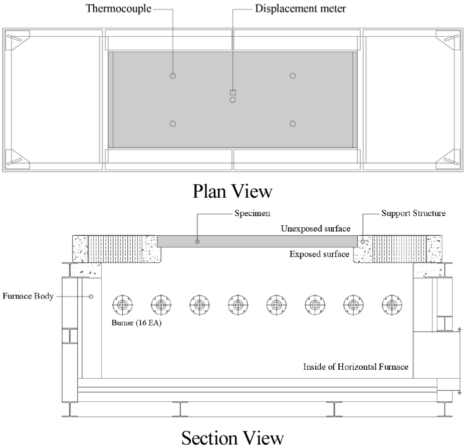
Figure 1 illustrates a horizontal furnace with a maximum testing area of 3000 x 4000. In order to facilitate the aforementioned test, a bespoke test frame has been constructed to provide the necessary support structure. Once the test specimen has been installed in the support structure, it is then installed in a horizontal furnace. A total of 16 burners are operated in order to conduct the fire test. The test specimen was supported at both ends in a manner that would reproduce the deflection that may occur in a real fire. The internal pressure of the furnace was set to 20 Pa, in accordance with KS F 2257-1, at the lower surface of the support structure. Thermocouples were attached at five locations to monitor surface temperature and deflection of the unexposed surface, and a displacement meter was installed in the center. Thermocouples were attached to the center and the center of each of the four sections, thus enabling the temperature distribution across the entire panel surface to be evaluated.
Following the conclusion of the fire test (a), as illustrated in Figure 2, the specimens were removed from the support structure (b) and subjected to fire extinguishing in accordance with the scenarios outlined in Table 2. Upon completion of the extinguishing scenario, the specimen was weighed and subjected to a simple bending test (c).
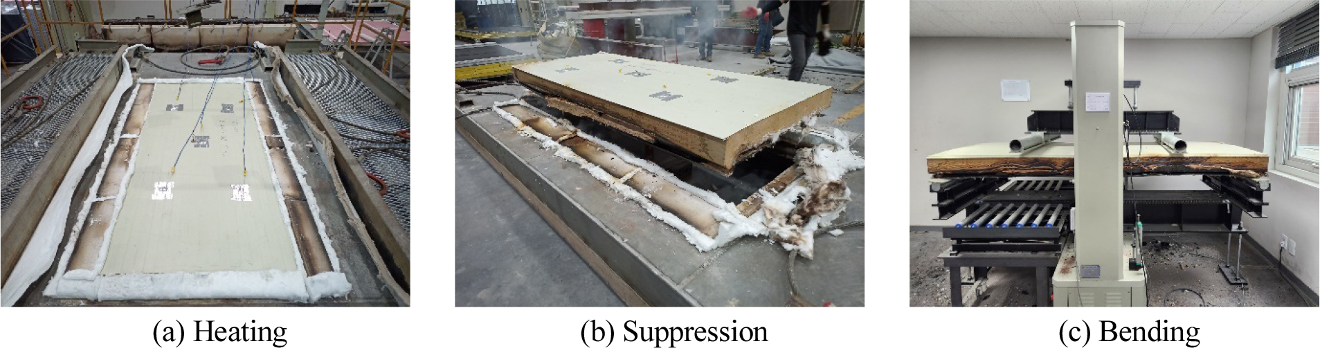
Table 2.
Core type and Suppression Scenarios
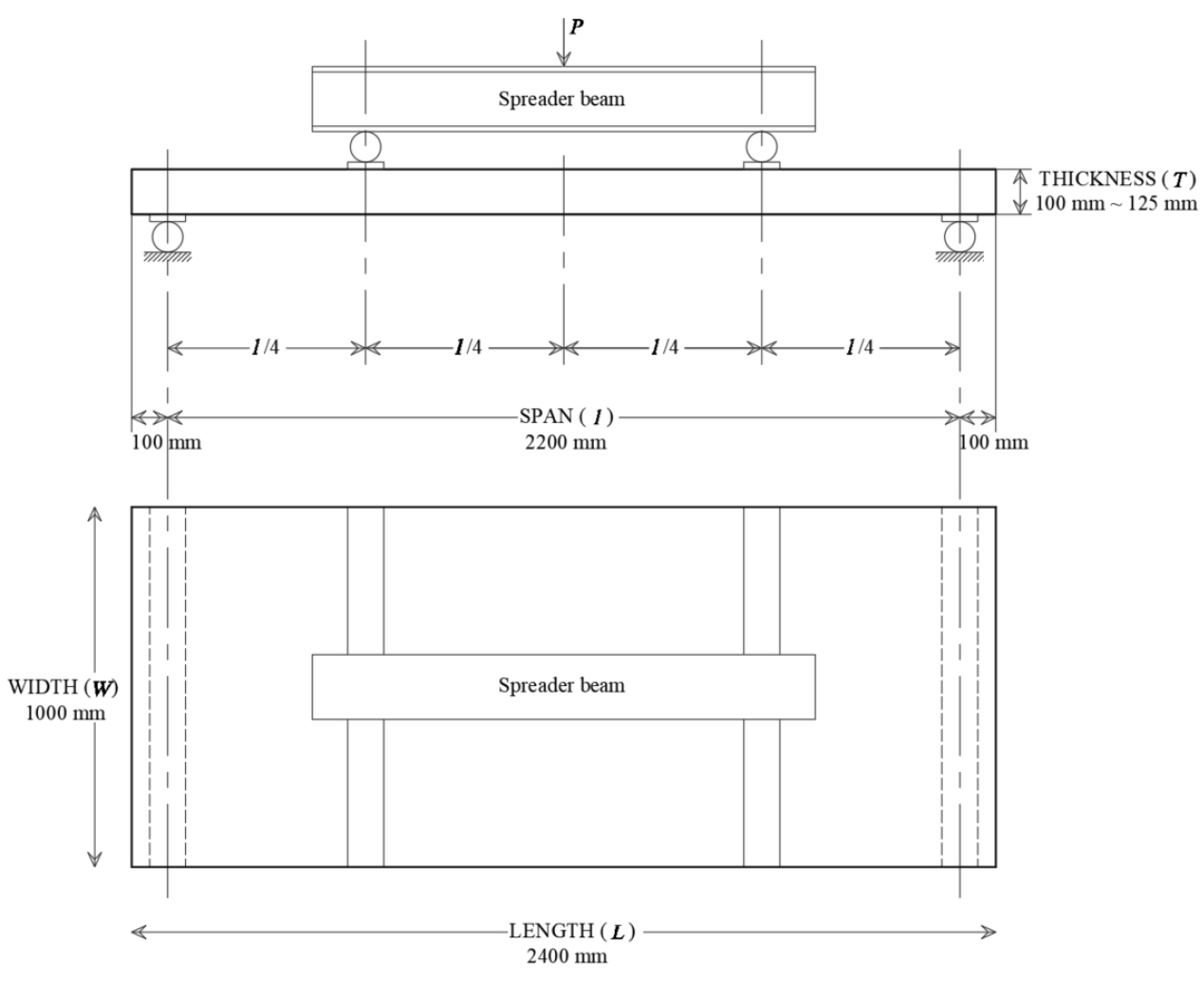
Following the fire test, the specimens that had been extinguished were subjected to a simple bending test. The simple bending test was conducted in accordance with the specifications outlined in KS F 2273 7.9. A simple bender with a spreader beam was employed to apply the bending at a quarter point of the span at both extremities, as illustrated in Figure 3. In the simple bending test, the end boundary condition was a simple support, and the specimen had a span of 2200 mm and an overhang of 100 mm. The strength of the specimen for this test is given by Equation (2), where Pmax is the maximum load on the specimen.
Specimen on Core material type
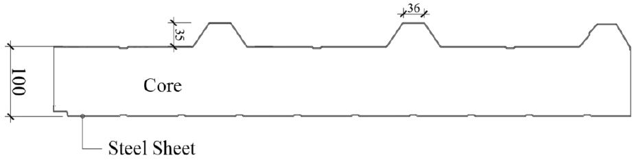
In the case of sandwich panels comprising organic core material, there is a possibility that flames may spread through the core material in the event of a fire. To investigate this phenomenon, urethane panels (THK:100 mm) with organic core material and glass wool panels (THK:100 mm) with inorganic core material were prepared for analysis. The dimensions of the test specimens are 1000 mm in width and 2400 mm in length, and their cross-sectional shape is identical to that of the roof, as illustrated in Figure 4. In consideration of the time required for fire recognition and subsequent reporting, as well as the arrival of the fire engine, the heating time in the event of a fire was set at 10 minutes [13]. Following a 10-minute heating period, three scenarios were tested, as detailed in Table 2. The first scenario involved room temperature cooling with a fire extinguishing cloth immediately after the end of heating. The second scenario involved room temperature cooling with a fire extinguishing cloth after 20 minutes in the furnace. The third scenario involved room temperature cooling with a fire extinguishing cloth after 20 minutes in the furnace, followed by cooling with a fire extinguishing cloth and watering. Each scenario was based on three cooling scenarios: extinguishing the fire immediately upon the fire truck’s arrival, extinguishing the fire after 20 minutes, and finally, spraying the structure with water after the fire was extinguished. Additionally, the undamaged sandwich panels underwent a simple bending test to facilitate comparison with the damaged specimens.
Specimen on Sectional Shape type
In order to determine the effect of cross-sectional shape on residual strength, simple bending tests were conducted after fire resistance tests on organic-based core material. The type of core material was the same urethane core material as the previous test, and three types of cross-sectional shapes were determined as shown in Figure 5, and the fire resistance tests were conducted by dividing the heating time as shown in Table 3. The heating time was increased by 10 minutes, 20 minutes, and 30 minutes, and the fire extinguishing method was the same after the fire resistance tests, and the fire extinguishing method was covered with a fire extinguishing cloth at room temperature. The cross-sectional shape was composed of three types: S-1 Roof type with three ridges on the top, S-2 Deck type with three ridges on the bottom, and S-3 Edge type with one ridge on the edge. All three products are certified as fire-resistant structures and are commonly used in the market. The size of the specimen, except for the cross-sectional type, was the same as all the tests in this study, 1000 mm wide and 2400 mm long, and the thickness of the core material was 125 mm. The overlapping flap of all types of specimens was removed for smooth fire resistance test.
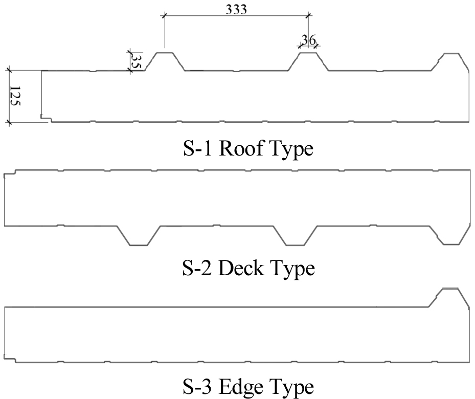
Table 3.
Sectional Shape type
Test Result
Core material type
As evidenced in Table 4, urethane panels exhibit markedly superior strength compared to glass wool panels in the unheated test case. Similarly, the urethane panel demonstrates superior performance in the strength test following the fire test, outperforming the glass wool panel. However, the urethane panel (C-1) exhibited an average strength loss of 86% after 10 minutes of heating, whereas the glass wool panel (C-2) demonstrated an average strength loss of 51%. Furthermore, it can be observed that the strength loss after 10 minutes of heating is consistent at approximately 51%, irrespective of the fire extinguishing scenario. In contrast, the percentage of strength loss after 10 minutes of heating for urethane panels varies from 84% to 87%, depending on the fire extinguishing scenario, with a maximum difference of 3% for each scenario. In the case of extinguishing the fire after a 20-minute waiting period, a 2% increase in strength loss was observed in comparison to the case of extinguishing the fire immediately following the test. In particular, the U-100-3 specimen exhibited the highest residual strength, having been cooled by direct water injection into the structure following fire extinguishing. The aforementioned results demonstrate that although the majority of strength is lost after heating, it is crucial to impede the spread of flame in the inner core through cooling by direct water injection into the structure to ensure the highest possible strength.
Table 4.
Maximum Strength and Deflection of C series
The findings of the residual strength test for the various types of core material indicate that organic material is more susceptible to fire damage than inorganic material. Moreover, the majority of the strength is lost following a fire, even when fire-extinguishing conditions are optimal. However, panels with an organic core still demonstrate higher residual strength than panels with an inorganic core, although there are discrepancies between scenarios. These results demonstrate that an organic core exhibits superior structural performance compared to an inorganic core, which is also corroborated by the deflection measurements.
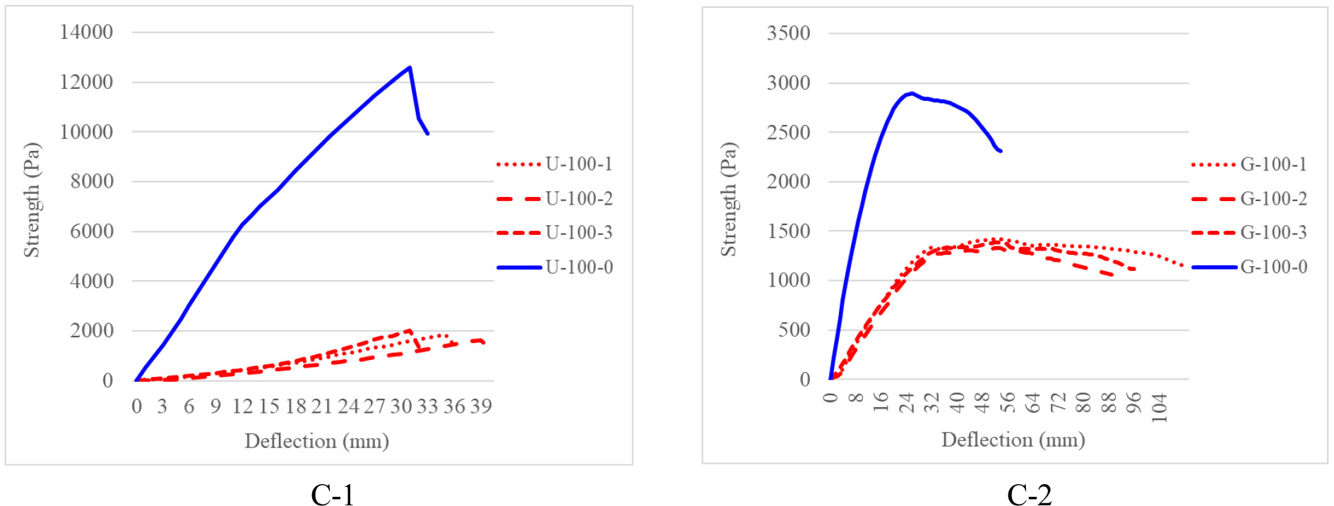
Figure 6 illustrates the strength-deflection curves for C-1 (urethane panel) and C-2 (glass wool panel). For C-1, a distinct deflection characteristic is evident for each extinguishing scenario. The deflection after 10 minutes of heating and immediate extinguishing (U-100-1) exhibited an increase of 9% in comparison to the unheated specimen, while the deflection after 20 minutes of waiting (U-100-2) demonstrated an increase of 21%. After a 20-minute waiting period, the extinguishing method through watering was not statistically different from the unheated case. In contrast, in C-2, G-100-1 exhibited the highest deflection, with a 109% increase compared to the unheated specimen. This was followed by G-100-2 with a 65% increase and G-100-3 with a 78% increase. It is notable that there was no clear correlation with the digestion scenario, in contrast to the observations made in C-1. Furthermore, it can be observed that C-1 reaches its maximum load and immediately fails without any further deformation. In contrast, C-2 demonstrates a ductile behavior in comparison to C-1, exhibiting significant deformation even after yielding. Notably, this ductile behavior is more pronounced after heating, irrespective of the extinguishing scenario, with an average increase in the maximum strain of 84%. Conversely, the maximum strain of C-1 increases by only 9% after heating.
Sectional Shape type
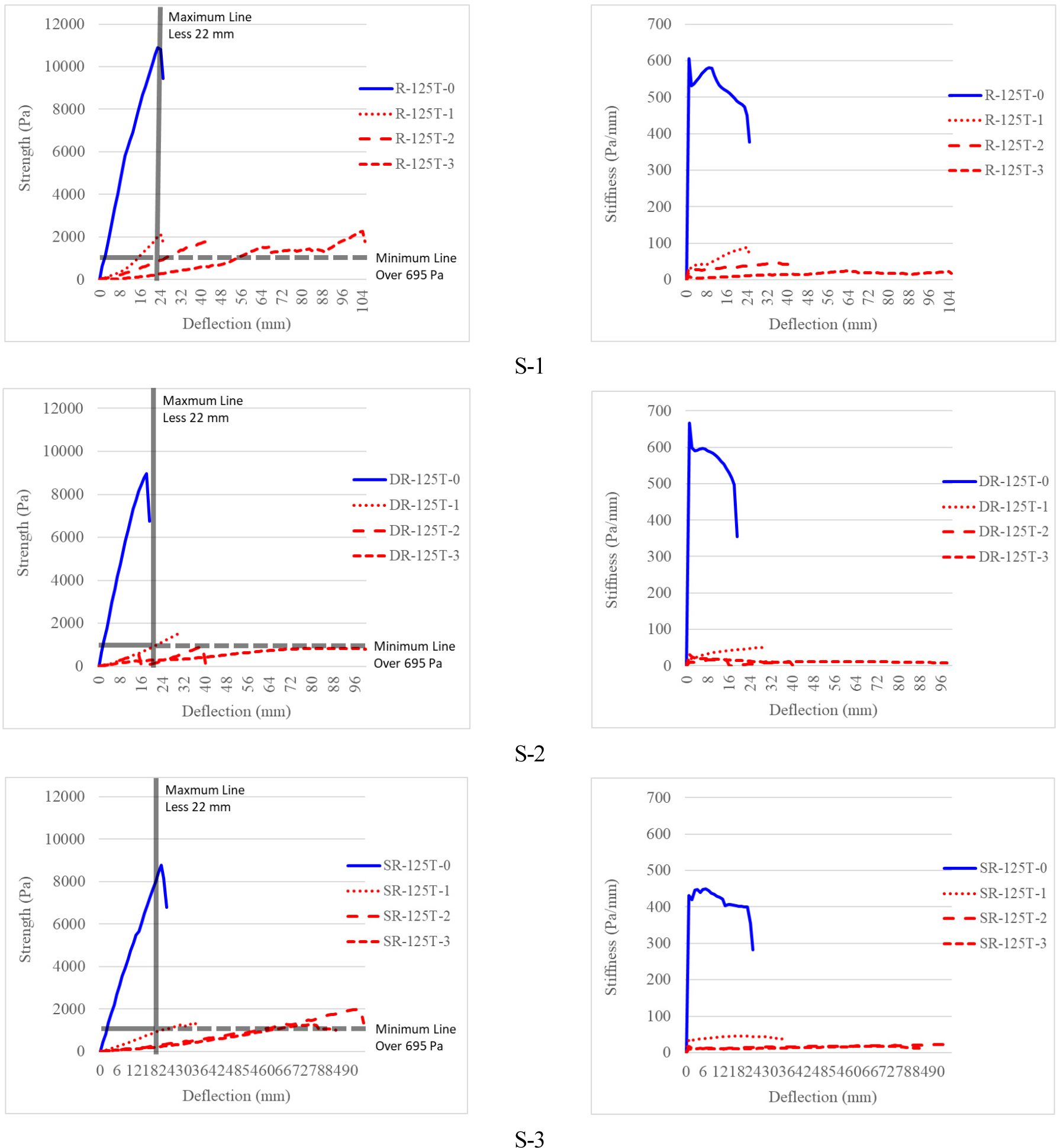
In order to investigate the residual strength of organic-based panels according to the cross-sectional shape, a total of 12 tests were conducted for three different cross-sections, as detailed in Table 3. The test specimen of S-1 (roof type) demonstrates the most robust residual strength, irrespective of the duration and temperature of the heating process. The mean strength was found to be 2064 Pa, which is approximately 81% less than that of the undamaged specimen. Subsequently, the S-3 (Edge Type) specimen exhibited an average strength of 1543 Pa, indicating a reduction of approximately 82% in comparison to the undamaged specimen. The S-2 specimen exhibited the lowest strength. The unheated specimen exhibited a strength of 8957 Pa, whereas the heated specimen demonstrated a significant reduction in strength, with an average loss of 90%. The residual strength exhibited no correlation with the increase in heating time, with values of 2135 Pa (10 min), 1789 Pa (20 min), and 2267 Pa (30 min) for S-1. These values were recorded at 10, 20, and 30 minutes, respectively. This was also observed in specimens S-2 and S-3. This phenomenon can be understood as resulting from the loss of adhesion and separation of the lower steel plate and heartwood, even after 10 minutes of heating. The bending deformation is subjected to compression on the upper surface and tensile force on the lower surface. The detachment of the lower steel plate causes the damaged core material, i.e. the urethane core material, to be subjected to tensile force, thereby rendering the structure vulnerable to bending deformation at the same time as the detachment of the lower steel plate. This is due to the difference in structural performance between the steel plate and the urethane material. Therefore, it can be seen that even if the heating time is increased, there is no significant correlation between strength and adhesion of the lower steel plate. This result indicates that the upper steel plate should bear the maximum load, as high tensile forces cannot be expected at the seam. The structural performance of the upper steel plate determines the post-fire strength after the fire.
In order to investigate the cross-sectional properties of steel plates and their relationship with strength, the moment of inertia of the S series test specimens was obtained. As shown in Figure 7, firstly, the moment of inertia of the top plate, bottom plate and core of each component was determined. Firstly, the moment of inertia of the top plate, bottom plate and core of each component was determined. Subsequently, the center of gravity of the entire panel was calculated. Subsequently, the moment of inertia was calculated by squaring the distance from the center of gravity of each component and multiplying the result by the area, as illustrated in Table 6. Tables 5 and 6 illustrate the correlation between the strength of the sandwich panel and the moment of inertia. It is evident that the initial stiffness is higher in the order S-2, S-1, and S-3 for the test specimen that has not sustained fire damage. This is due to the fact that the lower surface is subjected to tensile stress during the deformation process. The strength exhibited after the fire depends solely on the sectional performance of the top steel plate, as there is no strength to be expected from the remaining components, as previously explained. Consequently, it can be observed that the residual strengths are high in the order S-1, S-3 and S-2.
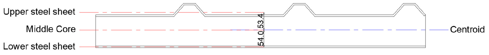
Table 5.
Maximum Strength and Deflection of S series
Table 6.
Moment of Inertia of S series
Figure 8 illustrates the cross-sectional shape subsequent to heating and the concomitant carbonization as a function of heating time. It can be observed that the extent of carbonization increases over time. This is corroborated by the test piece weights before and after heating, as presented in Table 7. The mean weight loss after 10 minutes of heating was 4%, with 11% and 17% weight losses occurring after 20 and 30 minutes of heating, respectively. As with the strength, the stiffness was predominantly lost. However, as illustrated in Figure 9, the stiffness exhibited a gradual decrease with heating time, while the strength did not correlate well with heating time.
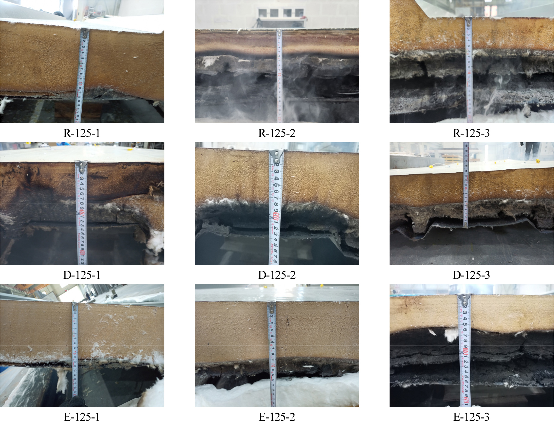
Table 7.
S series Specimen weight before and after heating (unit : kg)
Discussion
Table 8 delineates the requisite strength criteria that sandwich panels must satisfy when utilized as roofing materials. Table 8 indicates that a sandwich panel must exhibit a minimum strength of 695 Pa to be certified as a fire-resistant structure. This implies that the load corresponding to one-tenth of the span, the load representing 2.5% of the maximum strain, the load equivalent to two-thirds of the failure load, or the load that causes severe damage, whichever is the smallest, must be at least 695 Pa. Due to the limitations of the test equipment utilized in this study, only 1/100 of the span and 2/3 of the failure load were considered, and the criterion line is illustrated in Figure 9. As illustrated in Table 5 and Figure 9, the outcomes at 2/3 of the failure load surpassed the criterion, with the exception of D-125-2 and D-125-3. However, when the load of 1/100th of the span was considered, all specimens exceeded the performance standard after 10 minutes of heating. Of these, only R-125T-1,2 exceeded the performance standard after additional heating. This outcome can be attributed to the residual strength of the panel being contingent upon the cross-sectional performance of the top steel plate, as previously delineated. Additionally, the residual stiffness is attributable to the reduction in the panel’s area over the course of the fire, which consequently diminishes the distance between the panel’s center and the center of the top steel plate. This, in turn, results in a reduction in the panel’s stiffness.
Table 8.
Criteria of performance for building elements [14]
Table 9.
Average unexposed surface temperature and Deflection of S series according to Scenario 3
Table 9 illustrates the unheated surface temperature and deflection during the fire resistance test of the organic sandwich panel. The results presented here are derived from the 30-minute fire test. As illustrated in Figure 2(a), a total of five thermocouples were affixed to the center and four central sections for the purpose of measuring the temperature of the unheated surface. Additionally, a displacement meter was installed in the center for the purpose of measuring the amount of deflection. The mean temperature rise per section demonstrates the highest temperature rise in the R-125-3 specimen, though this is only 1.5°C. The strain was up to 27.6 mm in the SR-125-3 specimen, which represents an unpredictable underestimation of the collapse risk of sandwich panels in the event of a fire. It is recommended that the residual strength after the fire be measured to confirm the minimum stiffness, with the aim of facilitating the firefighters’ fire extinguishing work when firefighters enter the upper part of the roof to extinguish the fire.
Conclusions
Sandwich panels have many advantages, but they also have disadvantages: they are vulnerable to fire and can collapse under small loads. This experimental investigation allowed for a comprehensive analysis of the post-fire mechanical properties (stiffness and strength) of sandwich panels when used as roofing materials. A total of 20 specimens have been tested. Specifically, eight test specimens were organized according to the type of core material and fire extinguishing scenario, and 12 test specimens were organized according to the cross-sectional shape and heating time to conduct fire resistance tests and subsequent simple bending tests. The following main conclusions are drawn.
1)The organic urethane panels exhibited superior structural performance both before and after heating in comparison to the inorganic glass wool panels. Furthermore, it was confirmed that cooling with water is an effective method to minimize the loss of residual strength.
2)The residual strength of organic urethane panels depends on the cross-sectional properties of the top steel sheet regardless of the heating time, but the residual stiffness is determined by the heating time.
3)For a heating time of 10 minutes, all cross-section types exceeded the flexural criteria (695 Pa), but only the S-1 series (Roof Type) exceeded the criterion when heated for more than 10 minutes.
From the above conclusions, this study shows the need for the test method concerning the residual strength of the roof materials represented by the test specimen, after a fire. However, the proposed post-heating procedure and criteria are not sophisticated enough to carry out load/deflection testing and verification in practical manner. It is believed that future experimental studies on samples of more diverse shapes and sizes are needed.
