

Introduction
Plans for Surveying Actual Status
Assessment of Characteristics for Each Member through Core Specimens
Assessment of Compressive Strength through Core Specimens
Assessment of Resistance to Chloride Ingress
Assessment of Resistance to Chloride Ingress with Considerations for the Characteristics of Members
Overview of Assessment and Determination of the Location
Analysis of Strength Characteristics and Resistance to Chloride Ingress
Conclusion
Introduction
Reinforced Concrete (RC) structures such as bridges are becoming increasingly larger and are assembled with a wide range of structural members. In addition, different maintenance plans are established for each structural member since the localized exposure environment, strength grade, and load conditions are different. There has been extensive construction of superstructures using PSC-I type girders since the 1980’s in South Korea due to its constructability and structural efficiency, with the loading of slabs and I-type girders arranged in parallel format [1, 2].
In the case of carbonation, the deterioration degree (carbonation depth) can be easily evaluated through on-site survey using phenolphthalein indicator, on the other hand, in the case of assessment of chloride behavior, acid-soluble chloride assessment or electric charge assessment are usually executed by extracting core specimens [3, 4]. Curing conditions vary with the exposure environment even if it is concrete produced through the same mixing process, and status of deterioration is evaluated differently depending on the increase in the duration of public use. In recent years, corrosion of reinforcement due to chloride ingress has become a problem in metropolitan cities with the effects of de-icing materials used on the slabs or girders as the main cause [5, 6]. De-icing materials used during the winter causes cracks in the matrix due to continuous freezing and thawing, which in turn becomes the channel for additional influx of the source of deterioration-chloride ion. In addition, by elevating the surface temperature of concrete in a short period of time, it becomes the main cause of D-type cracks or pop-out of aggregates in structures with a wide specific surface area such as slabs [7, 8]. If leakage of water occurs from the top or in the event of occurrence of stagnant water in the drainage structure, such high concentration of chloride ion is passed onto the lower portion and the related corrosion of reinforcement due to de-icing agent are continuously being reported in the top portion of coping.
The substructures of bridges are constructed by way of on-site cast with the existence of quality fluctuations as they are large structures [9]. There is an increase in the influx of more deterioration factors in the construction joint and cold joint sections in comparison to sound sections, which accelerates corrosion of embedded reinforcement through chloride ingress or carbonation [10, 11]. In addition, even if cracks do not occur in the sections in which the flexural and tensile is dominant, an increase in the influx of deterioration factors in a gaseous state can occurs and the same phenomenon is found regarding permeability as well [12, 13]. Even if concrete placing is well carried out in the initial age, the hydration behavior changes due to sections protected against rainfall and sections continuously exposed to direct sunlight, which induces localized quality fluctuations in the concrete. Although an extensive range of research is being carried out on the assessment of chloride behavior of publicly used structures, estimation of the chloride diffusion coefficient relies mostly on simple regression analysis and experimental values in accordance with the mixing proportions [14, 15, 16][14, 15, 16]. Therefore, there are extensive limitations in reflecting the localized characteristics of actual structures. For superstructures of bridges, it has the composite structure of slabs with relatively low strength and PSC-I type girders with high strength. In this case, the influx of moisture of the upper part and the penetration of de-icing materials are expected along the bottom surface of the slab. In addition, it is very difficult to expect the excellent construction skills for the structures constructed in the 1970’s~80’s.
In this study, 60 core specimens were taken from the PSC-I type girders retrieved from the superstructures of a bridge used for 46 years in an urban area. Resistance to chloride ingress of the PSC girder is assessed for the cores specimens. Evaluation of accelerated chloride diffusion coefficient through NT-BUILD 492 and chloride passed charges through ASTM C 1202 were conducted [21, 22]. In addition, exposure conditions, strength, and resistance to chloride ingress characteristics were considered through assessment of the core strength at the corresponding location.
Plans for Surveying Actual Status
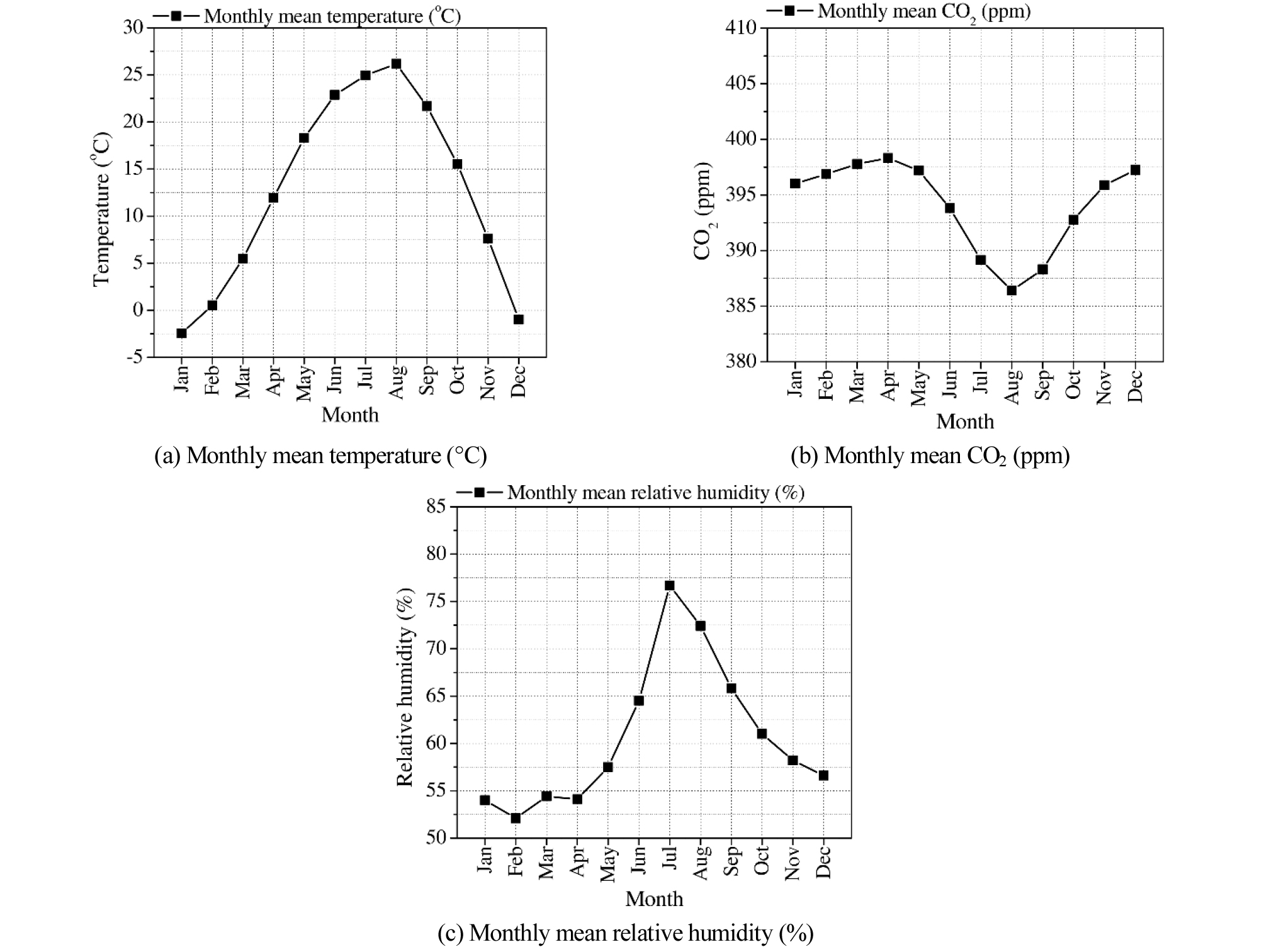
The bridges for this work were located in Seoul-metropolitan city in South Korea and have been exposed to environmental conditions-the average annual temperature of 12.6°C and annual average relative humidity of 60.6% of the last 10 years with the average atmospheric CO2 concentrations found to be in the range of 386~398 ppm [17]. In addition, it was possible to determine the extent of the deterioration in the bridge from the results of precision safety diagnosis conducted prior to dismantling of the bridge, which reporting an insufficient concrete cover in the deteriorated areas, the progress of cracking, and spalling of concrete cover due to carbonation [18]. The target structure was composed of RC slabs and PSC-I type girders, and the specified compressive strength of concrete found to be 24 MPa and 35 MPa for slabs and girders, respectively. Figure 1 illustrates the exposure environment the target structures were subjected to.
Assessment of Characteristics for Each Member through Core Specimens
Assessment of Compressive Strength through Core Specimens
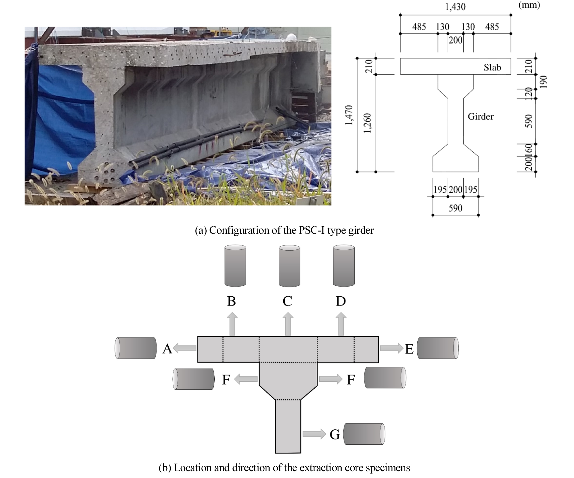
71 and 47 cores were extracted from the slabs and girders to assess the compressive strength of concrete. Compressive strength test of core specimens was executed in compliance with the Korean Standard Test Method (KS F 2422 and KS F 2405) [19, 20]. The state of the core specimens and the images of the PSC slab and girder after extracted core specimens are illustrated in Figure 2.
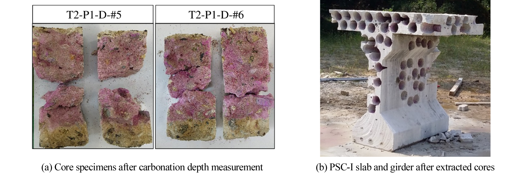
As shown in Figure 2, the girder was cut into three segments of the length 1 m. Figure 2(b) shows one of the three segments. The cores were extracted from each segment for mechanical properties and durability tests. The averages of carbonation depth were measured to 16.7~18.2 mm (COV:33.6%) for girders and 22.7~30.6 mm for slab (COV 19.9~32.9%), respectively.
Assessment of Resistance to Chloride Ingress
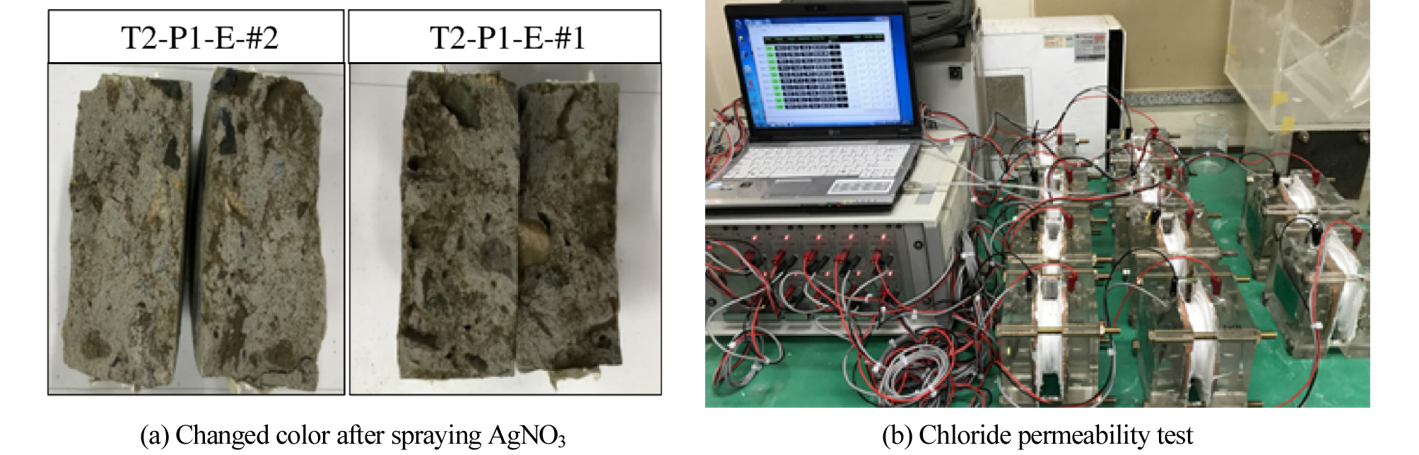
Accelerated chloride diffusion coefficients were measured in accordance with NT BUILD 492 after extracting core specimens, and total passed charges is done in accordance with ASTM C 1202 for assessment of resistance to chloride ingress rating. Equations (1), (2) and (3) are the accelerated chloride diffusion coefficient equations and Table 1 illustrates the outline diagram of the experiment [21, 22]. Equation (4) shows the total passed charge equation with the Table 1 displaying the classifications for assessment of the charges. Photographs of discoloration due to silver nitrate and photos after the accelerated chloride diffusion test are given in Figure 3.
Table 1. Test condition for NT BUILD 492
| Condition | Levels | Set up | |
| Electrolyte | Cathode | 10% NaCl | 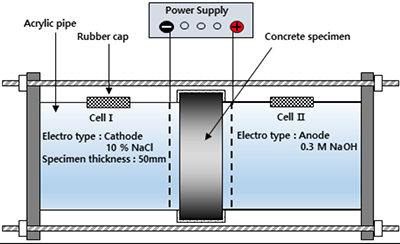 |
| Anode | 0.3 M NaOH | ||
| Applied voltage(V) | 30 | ||
| Applied time(Hour) | 8 | ||
| Thickness(mm) | 50 | ||
| $$D_{rcpt}=\frac{RT}{zFE}\frac{xd-a\sqrt{x_d}}t$$ | (1) |
| $$E=\frac{U-2}L$$ | (2) |
| $$a=2\sqrt{\frac{RT}{zFE}erf^{-1}\left(1-\frac{2C_d}{C_0}\right)}$$ | (3) |
| $$Q=900(I_0+2I_{30}+2I_{60}+\dots+2I_{330}+I_{360})$$ | (4) |
Here, = DrcptAccelerated chloride diffusion coefficient (m2/sec)
R = Gas constant (8.314 J/mol ․ K),
T = Absolute temperature (K)
z = Ion electrovalence (1.0)
F = Faraday constant (96,500 J/V ․ mol)
U = Potential difference (V)
L = Thickness of specimen (m)
xd = Average value of the penetration depths (m)
t = Test duration (sec)
Cd = Chloride concentration at which the color of the silver nitrate indicator changes (mol/l), and
C0 = Chloride concentration in the catholyte solution (mol/l).
Q = Passed charges (Coulomb)
Ix = Current (A) at x minutes.
Assessment of Resistance to Chloride Ingress with Considerations for the Characteristics of Members
Overview of Assessment and Determination of the Location
Cores were extracted for each of the locations in the PSC-I type girder. They were extracted in the right angle direction of the cut surface at sections A and E (left and right cross-section of the slab), and in the vertical bottom direction with the slab at sections B, C and D (center of the slab). In the case of girder, cores were extracted from the left and right side of section F on the top flange and section G in the web of the girder. Figure 4 illustrates the location and drilling direction of core specimens as well as the configuration of the PSC-I type girder. A total of three girders were cut up for the extraction of cores, and diffusion coefficients and their passed charge were analyzed considering each location.
Analysis of Strength Characteristics and Resistance to Chloride Ingress
Analysis of Strength and Resistance to Chloride Ingress Characteristics of the Subject Girder
The sections of A and E have the member of being compressed in the longitudinal direction and bent in transverse direction. The height of the I-type girder is 1,470 mm so that strength decreases at the time of manufacturing of the top portion concrete in comparison to the bottom portion. Although compressive loading works more greatly in the longitudinal direction in the case of sections B and D, it is not an environment of direct exposure to rainfall since it has composite action with top slab. In the case of F and G sections, it is not a tapered surface section with difficulties in cast and is exposed to a relatively good curing condition for a long time. Table 2 displays a summary of the average values and COVs (Coefficient of Variation) in accordance with each position while Table 3 illustrates the standards for assessment of resistance to chloride ingress presented under ASTM 1202 with high permeability of more than 4000 C for all.
Table 2. Mean and COV with different location of core specimens
Table 3. Chloride penetration resistance referred to ASTM C 1202
| Passed charges | Grade |
| > 4,000 | High |
| 2,000 ~ 4,000 | Moderate |
| 1,000 ~ 2,000 | Low |
| 100 ~ 1,000 | Very low |
| < 100 | Negligible |
As can be seen from the results of the strength assessment, the strength of the target structure was found to be much low due to the lack of casting ability and non-uniformity of the materials at the time of construction. In the case of Type I Portland cement thought to have been used in the mixing of the concrete at the time of construction, it has lower chloride resistance in comparison to the mixture that uses Ground Granulated Blast Furnace Slag (GGBFS) or Fly Ash (FA). This is because it is not possible to expect fortification of chloride adsorption resulting from the reduction of pore structure and increase in hydrides due to continuous latent hydraulic property or pozzolan reaction property [22, 23][22, 23].
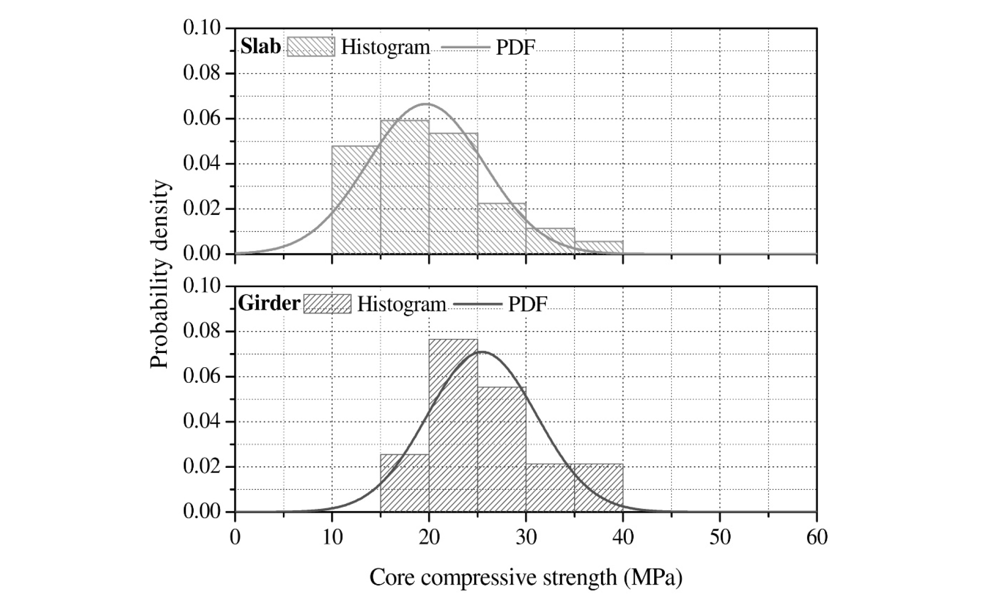
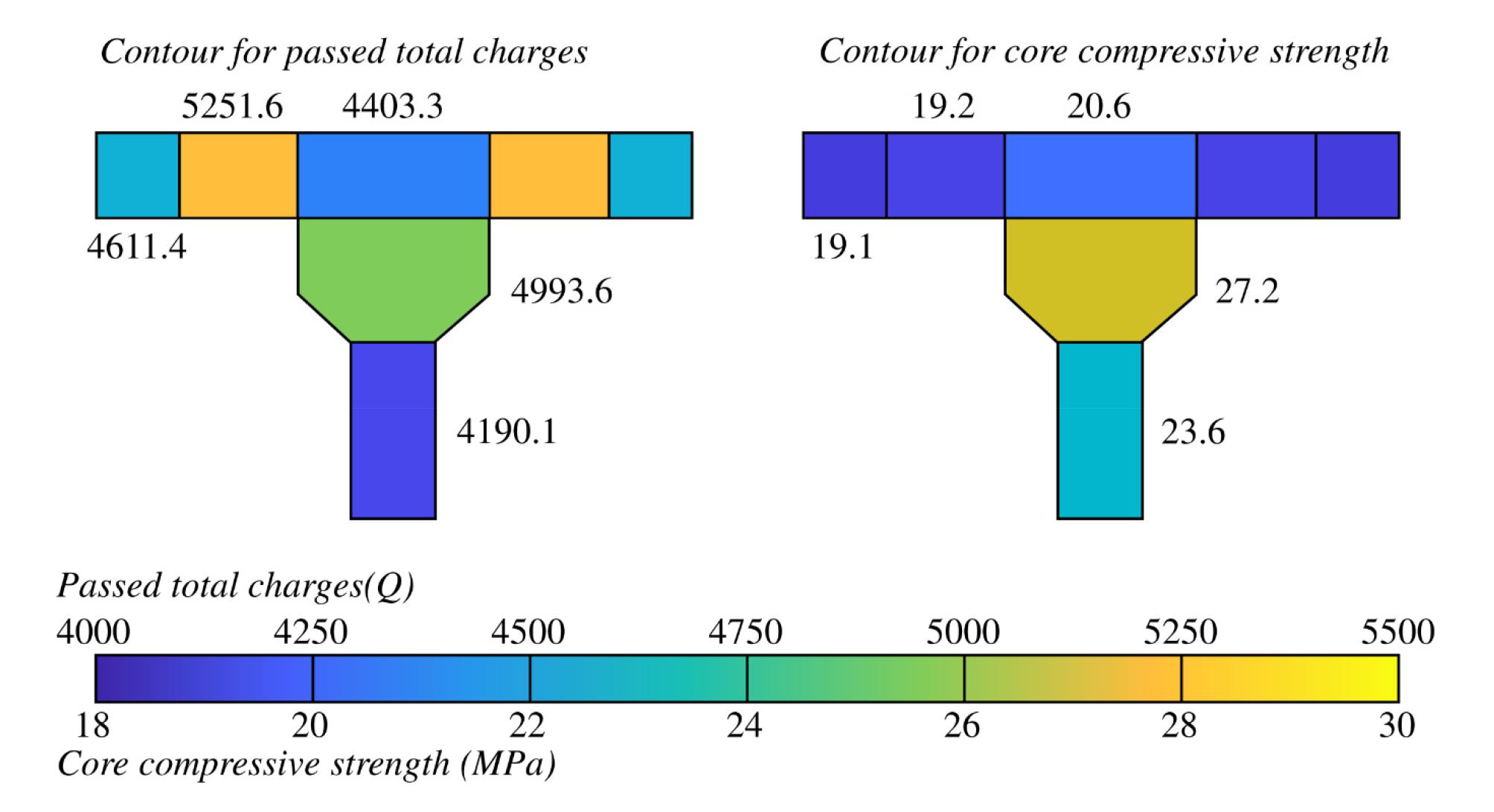
Table 4 illustrates average compressive strength, standard deviation (STD), and coefficient of variation (COV) of the cores extracted from slab and girder. The compressive strength of the cores of slab and girder was measured to be lower than the design compressive strength. In particular, the compressive strength of the core collected from the G section is at 67% level of design strength, thereby displaying the largest reduction in strength compared to other sections. Figure 5 illustrates the histogram and probability distribution function of the core compressive strength of slabs and girders. Although the distribution of core compressive strength of slab and girder does not display significant differences, the coefficient of variation of compressive strength of slab was analyzed to be larger than that of the girder. Strength characteristics and passed charge variation (C) in accordance with the location of the collection of each core were schematized as a contour and illustrated in Figure 6.
Table 4. Mean, STD and COV of core compressive strength with different locations
| Location | Slab | Girder | |||
| A,E | B,D | C | F | G | |
| Mean (MPa) | 19.1 | 19.2 | 20.6 | 27.2 | 23.6 |
| 19.7 | 25.5 | ||||
| STD (MPa) | 6.0 | 5.6 | |||
| COV (%) | 31 | 22 | |||
Chloride Ingress and Strength Characteristics for Each Core Location
Passed charge range of 3048~6449 C and diffusion coefficient range of 4.0~16.3×10⁻¹² m2/sec were measured in the A and E sections. Since there was no direct exposure to rainfall, the design strength of slab was 24 MPa and the core strength was 19.1 MPa in this section. Since it has average passed charge of 4164 C and assessed as HIGH, thereby having poor resistance to chloride ingress. As it can be seen from the results of strength assessment, it has low strength and low resistance to chloride ingress.
Since the B and D sections were measured at the base of the slab, it is expected to be protected against rainfall and progress of carbonation due to influx of CO2. In particular, it is a structure that resists bending in a transverse direction and the passed charge and diffusion coefficient were assessed to be the largest. Passed electrical charges were in the range of 2225~7636 C while the diffusion coefficient was in the range of 5.3~18.8×10⁻¹² m2/sec. It was assessed as being the section with the severest deterioration due to such factors as the effects of continued bending load and lowered quality arising from girder height. Although water and air permeability of the surface are improved at the time of the progression of carbonation in the case of OPC-based concrete, it is known that the chloride resistance on the overall cross-section is reduced as the internal calcium hydroxide is converted into calcium carbonate. Although the quantity of chloride in the carbonated concrete displays the gradient that moves from the surface to inner side in many researches [24, 25], research on the diffusivity of the overall cross-section is clearly reported. Since it is the base of the slab, it has a design strength of 24 MPa and a low compressive strength of 19.2 MPa. It can be seen that it has poor strength and resistance to chloride ingress with the average passed charge assessed to be very large at 5251.6 C.
In the case of C section, it is anticipated that there would be almost no effect of carbonation since it is a structure that borders the top slab and paving structure. It has passed charge in the range of 3494~7843 C and the diffusion coefficient in the range of 9.8~19.2×10⁻¹² m2/sec. It belongs to the most satisfactory section among the measured values with average passed charge of 4403.3 C and core strength of 20.6 MPa since it is subjected to lesser effect of transverse loading and deterioration with direct installation at the top-center section of the I-girder.
F section is the top flange of girder with relatively large passed charge and diffusion coefficient deduced. It is peculiar that variability is assessed to be relatively low and this is deemed to be the result of the mid-level height of the cast and protection against rainfall. The passed charge is in the range of 3629~6825 C and the diffusion coefficient is in the range of 10.1~17.1×10⁻¹² m2/sec, while the average passed charge is found to be 4993.6 C and core strength measured at 27.2 MPa. Although it is at 77.7% level of the design strength of girder at 35 MPa, it has relatively high strength in comparison to that of the slab.
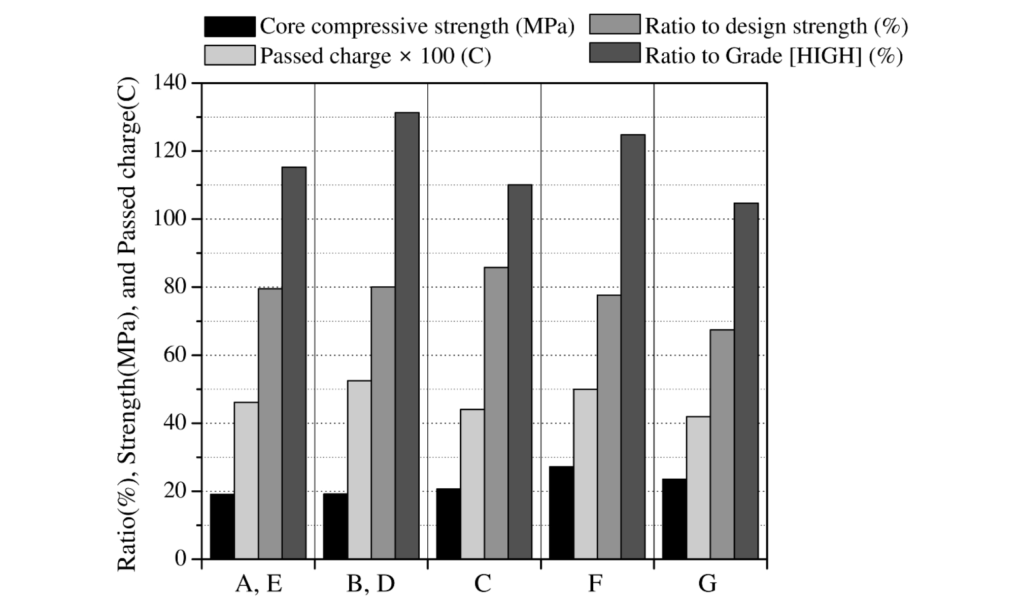
The G section was found to be the most outstanding section and is the section in which the largest compressive force is passed on due to prestressing force. The passed charge is in the range of 2278~5782 C and the diffusion coefficient is in the range of 6.8~14.9×10⁻¹² m2/sec. Since this section has the lowest surface at the time of cast, it has good quality of concrete with relatively good durability characteristics due to the introduction of compressive stress. The average passed charge is the lowest at 4190.1 C and the core strength is 23.6 MPa. Figure 7 illustrates the average passed charge and strength in accordance with the location of the core collection.
Conclusion
In this study, concrete cores were obtained from the slabs and I-type girder retrieved from PSC bridge used for 46 years in an urban area, and their strengths and resistances to chloride ingress were assessed in accordance with the exposed environment and location of the extraction core specimens. Conclusions reached through this research are as follows:
1)Compressive strengths of cores extracted from slab and girder were measured to be lower than the design compressive strength, and the compressive strength of G section (web of girder) was evaluated to be reduced markedly to 67.4% level of the design strength in particular.
2)In the A and E sections (lateral side of the slab), the average passed charge was 4164 C and the core strength was 19.1 MPa, along with the corrosion rating at the level of 115% of [HIGH] rating and 80.0% level of the design strength. B and D sections (bottom surface of slab) were found to have the largest passed charge and diffusion coefficient. The average passed charge was 5251.6 C and the core strength was 19.2 MPa, thereby being assessed as the most deteriorated location. In the case of the C section (central portion of the slab), it has the most satisfactory state among all the measurement values with average passed charge of 4403.3 C and the core strength of 20.6 MPa.
3)The F section (top flange of girder) has relatively low fluctuation in the strength and resistance to chloride ingress because the height of cast is at about the middle level and it is protected against direct rainfall. The average passed charge was 4993.6 C and the core strength was 27.2 MPa, which is at 77.7% level of the design compressive strength. G section (web of girder) is the most satisfactory section in which the largest compressive stress is applied due to prestressing. The average value of passed charge is the lowest at 4190.1 C with the core strength at 23.6 MPa.
4)The degree of deterioration and the extent of resistance are evaluated differently for the slab and girder since their design strength and local exposure conditions are different. In this study, the vulnerability was investigated by the bottom surface of slabs exposed to the atmosphere. In the case of girders, the strength and resistance to chloride ingress of the top portion is assessed to be lower in comparison to those of the bottom portion. The results of this study can be used as basic data to determine the grade and priority for repair and maintenance.
