

Introduction
A structure experiences two different kinds of lateral forces namely wind and earthquake, both these forces cause dynamic actions on the structure. However, the design parameters for both these loads are widely different. In case of wind loading, the structure is subjected to the pressure arises due to wind forces on its exposed surface whereas in case of earthquake it is subjected to random motion in the horizontal plane, which causes stresses and displacement. Taking different types of loading into consideration, the buildings are designed and detailed to develop a proper failure mechanism with adequate strength and stiffness in all its members. The design and detailing of a structure depends on various aspects like geometry, plan size, bay length, shape and size of members, etc. The geometry of structures can be categorized as convex or concave. The concave geometry show a better performance during earthquake. The convex shaped structures transfer earthquake forces due to ground shaking through load paths whereas in concave structures the bending of load paths in different directions resulting in stress concentration at those points.
The normally built structures can be categorised as simple or complex. The structures with regular geometry show a better performance as the load transfer is along load paths without any bend in them. However, structures with openings, offsets and setbacks create discontinuity in the load transfer before terminating into ground leading to bends and higher stress concentration at such points. A structural designer must ensure the structural safety of the structure against the worst possible combinations of loads. From the above discussion, it can be concluded that both structural and non-structural damages are observed during earthquake ground motions are primarily produced by lateral displacements and specially in open configurations. Therefore, in order to increase the seismic strength of framed structures, structural walls are often used. However, considering the ease of construction and the relatively low cost, structural walls appears to be a better alternative. It was therefore considered necessary to carry the present study on seismic analysis of RCC framed structures with floating columns.


Thus, introduction of floating columns in a structure introduces discontinuity in the load path especially whenever a column coming from upper storeys is discontinued at the lower level like the ground storey.
In this type of a arrangement, the load from overhanging portion travel from the nearest columns to the foundation below. Therefore, this demands to design the columns on lower level with higher load carrying capacity and higher chances of failure in such columns. Another common example of discontinuity is due to setback columns, such a situation arises when the centreline of column coming from top is moved on the lower levels. In the setback columns, the load causes stress concentration at the point of discontinuity while transferring to the nearest columns. Hence, the structural design for floating columns should be done carefully and cautiously to avoid any failures in the connecting beams and nearby columns.
Bandwal [1] studied the architectural complexities and irregularities and analyzed floating columns at various level and location. The main focus of their study was to check the behaviour of such buildings during earthquake. The loading due to earthquake in their structure was considered according to IS 1893(Part 1):2002. The study analysed the critical position of internal floating columns, external floating columns of G+6 . The author with the help of significant graph, compared and corelated various parameters like displacement, moments and forces on columns and beams at various floor levels. The study concluded that the torsional effect is experienced to a significant amount at the ground level. On the other hand, in the work presented by Rohilla [2], the need of floating columns in highly populated areas, their behaviour and advantages have been discussed. They highlighted that the floating columns are not suitable for the earthquake active areas because in absence of a column there is no path for the earthquake forces to get carried down in the ground. Building of G+5 and G+7 for zone 2 and 5 having irregular architecture were analysed in their research. Authors concluded that floating column should be avoided in high rise building specially in earthquake zone 5 as it leads to storey displacement. However, increasing the size of beam and columns in building having floating columns can improve the strength manifolds. Bhensdadia [3] conducted the study on the effect of floating column and soft storey in different seismic zones. In their study the performance of design capacity of the building has been carried out up to failure, where push over analysis has been adopted for determination of collapse load and ductility capacity of the structure. The authors have also used SAP 2000 software analysis package, to analyse three RC framed structures with G+4, G+9, G+15 storey. They concluded that the push over analysis is the accurate and efficient method of analysis and the displacement of all models are less for lower zone and it goes on increasing through the higher zones. On the other hand, the study carried out by Patil [4] analysed an RC Building G+5 storey for different seismic loading. The authors analysed three different models namely the normal structure, shear wall structure and masonry infill wall structure by equivalent static method approach, response spectrum approach and time history approach. Etabs software has been proved to be useful for the analysing the parameters. The study concluded that a multi-storey building with shear walls perform best in earthquake prone areas. Meanwhile, the outcome of a floating column under earthquake for various soil conditions were studied by Nautiyal [5]. Their analysis were carried out on two models considering four storey and six storey building with special moment resting frame. The authors made a variation in the positioning of floating columns in the study, by lifting some from the first floor, some from second floor and some from third floor. They concluded that, for a medium density soil, the base shear value were found higher than that of a high density soil for both the models. Mundada [6] studied the architectural and structural frame drawing of existing G+7 residential building. They carried out equivalent static analysis on three models, where building with floating columns, building without floating columns and building with floating column and struts were analysed in Staad pro. They concluded that the deflection and possibility of failure with floating column is much more than the floating column with struts. Malaviya [7] studied the aftermath on the cost analysis of structures design done with staad pro. A 15m X 20 m G+1 symmetrical structure building with floating column and without floating columns were considered for the study. Based on modelling, design and estimation of the building the author concluded that the weight of concrete and steel is more in the case of building with floating columns than the building without floating columns and with the change of positioning of floating column, the quantity steel and concrete also changes which makes the structure high demanding in terms of funds. Srikanth [9] carried out studies on four models i.e., FC (floating column provided in particular floor, location), FC+4 (floating column provided by rising height by 4 m), FC+HL (floating column provided by applying heavy load), FC+4+HL (floating column provided by rising the storey height by 4 m and applying heavy load in combination). The design methodology employed a fully combined process that allow modelling, analysing, designing. The author concluded that a complex building undergoes whiplash effect under earthquake shaking such as seen for FC+4+HL building. The models experience less displacement value for lower zones which goes on increasing through higher zone.
Methodology
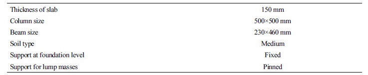
The building under study is symmetrical in plan with area of 25 m × 20 m and has G+10 storeys. It has 5 bays of 5m each in X direction and 4 bays of 5 m each in Z direction. The storey height of each floor is 3.00 m and depth of foundation as 2 m. The building was considered in Zone IV. The grade of concrete for columns was M30 and M25 for beams. The building was to be used for residential purpose and the ductile detailing of steel was done as per Indian standard code (IS) 13920:1993 for special moment resisting frame. The other parameters of building was as follows:
The building was analysed for different location of floating columns to assess the most preferred position to construct them in a structure. Based on the location following cases have been studied in detail:
1.MODEL A:- G+10 regular RCC building without floating columns.
2.MODEL B-1:- G+10 regular RCC building with six internal floating column at ground floor roof.
3.MODEL B-2:- G+10 regular RCC building with six internal floating column at third floor roof
4.MODELB-3:- G+10 regular RCC building with six internal floating column at six floor roof.
5.MODEL B-4:- G+10 regular RCC building with six internal floating column at ninth floor roof.
6.MODEL C-1:- G+10 regular RCC building with six external floating column at ground floor roof.
7.MODEL C-2:- G+10 regular RCC building with six external floating column at third floor roof.
8.MODEL C-3:- G+10 regular RCC building with six external floating column at six floor roof.
9.MODEL C-4:- G+10 regular RCC building with six external floating column at ninth floor roof.
10.MODEL D-1:- G+10 regular RCC building with six external and internal floating column at ground floor roof.
11.MODEL D-2:- G+10 regular RCC building with six external and internal floating column at third floor roof.
12.MODEL D-3:- G+10 regular RCC building with six external and internal floating column at six floor roof.
13.MODEL D-4:- G+10 regular RCC building with six external and internal floating column at ninth floor roof.
Loading:
Various types of load considered are as below:
Dead Load : The dead load on all floors was considered as 5.3 KN/m2 and on terrace as 7.3 KN/m2. The wall load of inner 4.5” thick brick wall was taken as 7.5 KN/m and that of outer 9” thick brick walls was taken as 12.7 KN/m (after deductions for openings). The load for parapet wall was calculated as 5 KN/m
Live Load : As per IS 875 (Part 2):1987 the live load had been taken as 3.00 KN/m2 for intermediate floors and 1.5 KN/m2 for roof.
Seismic Load : As per IS-1893-2002, the dynamic analysis was performed using Response Spectrum Method. In response spectrum method design parameters for horizontal seismic coefficient were as below:
Z, zone factor = 0.24
I, importance factor = 1
R. response reduction factor = 5
Damping ratio = 0.05
Load combinations: The different load combinations to be analyzed were as per IS 87 5(Part 3):1987 as illustrated below :
1.1.5D.L. + 1.5L.L.
2.1.2( D.L. + 0.5 L.L. + (EQ +X))
3.1.2( D.L. + 0.5 L.L. + (EQ +Z))
4.1.2( D.L. + 0.5 L.L. + (EQ -X))
5.1.2( D.L. + 0.5 L.L. + (EQ -Z))
6.1.5( D.L. + (EQ +X))
7.1.5( D.L. + (EQ +Z))
8.1.5( D.L. + (EQ -X))
9.1.5( D.L. + (EQ -Z))
10.D.L. + L.L.
Results and Discussion
In the present study, the building frames have been analyzed using STAADPRO-2008, which is based on stiffness matrix method of analysis. Discussion of results is done in subsequent sections:
A. Base Shear:
From Table 1 to 3 it is evident that base shear value slightly increase of 0.82 % in x direction at ninth floor roof and decrease of 0.72 % at ground floor roof of internal floating columns and combination of internal and external floating columns, whereas from Table 2 records the max percentage decrease of 7.28 % at ninth floor roof and increase of 1.13 % at sixth floor roof of external floating column. This is because with the increase in spectral acceleration the horizontal seismic coefficient (Ah) increases
Table 1. Comparison of base shear of a RCC building having six internal floating at different heights 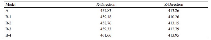 |
Table 2. Comparison of base shear of a RCC building having six external floating at different heights 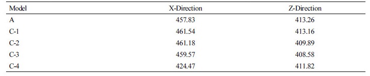 |
Table 3. Comparison of base shear of a RCC building having six internal & external floating at different heights 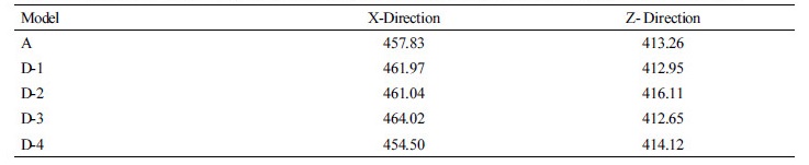 |
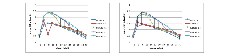
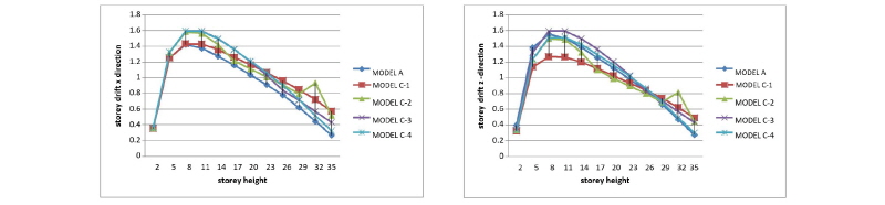
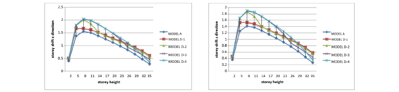
B. Storey Drift:
The results of the drifts are shown in Figures 3 to 5 for all cases. As per IS 1893:2002, the storey drift in any story due to minimum specified design force shall not exceed 0.004 times the storey height. From the analysis results, it is found that a regular building without floating columns and internal floating columns at ground level are within permissible limits. Graphs (Figures 3 to 5 are plotted between drift (in cm) and storey height (in meters) while in building with external floating column at different levels are exceeding the limits.
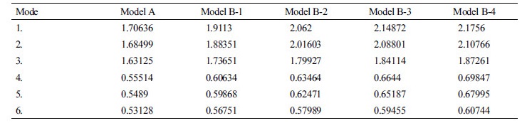
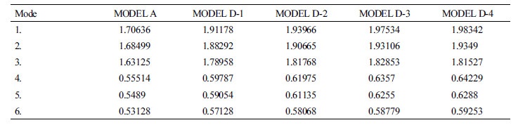
C. Time Period
From Table 4 to 6 it is evident that with the addition of floating the fundamental time period of the building increases. Comparing model A to model B there is a max percentage increase time period of 27.52% at ninth floor roof (Table 4) and also comparing model A to model D percentage increase time period of 16.06% at ninth floor roof (Table 6). From bar charts (Table 5) there is slightly increase of 5.5% is seen in external floating column G+10 building.
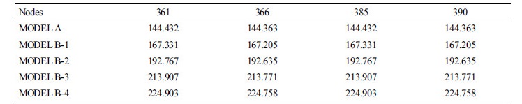
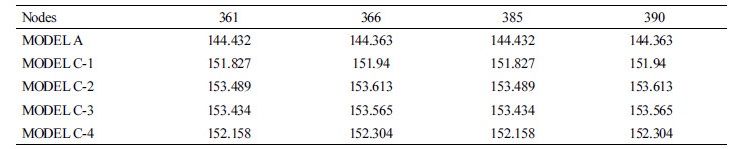
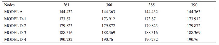
D. Deflection
From Table 7 to 8 the four corner nodes (361, 366, 385, 390) of all the models shows deflection value taken under critical load combination. It is evident that with the addition of floating the deflection of the building increases. Comparing model A to model B there is a max percentage increase deflection of 55% (Table 7) and also comparing model A to model D percentage increase in deflection of 32.05% (Table 9). After comparing model C with model A (Table 7) a increase of 6.23% is seen in external floating column G+10 building.
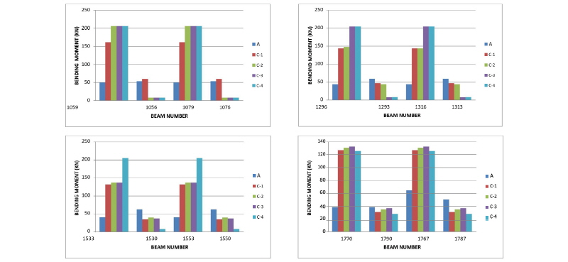
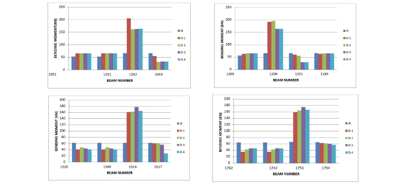
E. Bending moment in beam
The results of bending moment (in kN-m) in beams are plotted in bar charts shown in Figures 6-9.
Comparison of bending moment in beams between model A and model B
Bending moment at the first floor, fourth floor, seventh floor and tenth floor level columns for model B is plotted (Figures 6-9). Various typical beams are selected. The member numbers selected for first floor are 1066, 1042, 1043, 1065, member numbers for fourth floor level are 1302, 1303, 1279, 1280, member number for seventh floor level are 1539, 1540, 1516, 1517 and member number for tenth floor level are 1776, 1777, 1753, 1754.
From Figures 6 to 9 it is evident that bending moment is increases when floating columns are provided. This is due to improper formation plan of model due to which the lateral load produces the stresses into the beam and increases the bending moment. From bar charts it is clear that model B-4 building show least bending moment in beams. By comparing the results it was seen that the least bending moment in case of model B building is observed at tenth floor level and max bending moment at the first floor level. So there is max 38.8% reduction in member number 1517. Similarly, there is a max percentage increase of 71.89% in member number 1065.


Comparison of bending moment in beams between model A and model C
From Figure 10 it is evident that bending moment is increases when floating columns are provided. This is due to improper formation plan of model due to which the lateral load produces the stresses into the beam and increases the bending moment. From bar charts it is clear that model C-4 building show least bending moment in beams. It was seen that the least bending moment in case of model C building is observed at tenth floor level and max bending moment at the first floor level. So there is max51.13% reduction in member number 1780. Similarly, there is a max percentage increase of 71.89% in member number 1059.
Comparison of bending moment in beams between model A and model D
From Figure 11 it is evident that the bending moment increases when floating columns are provided. This is due to improper formation plan of model due to which the lateral load produces the stresses into the beam and increases the bending moment. From bar charts it is clear that model D-1 building shows least bending moment in beams. By comparing it is evident that the least bending moment in case of model D building is observed in first floor level and maximum bending moment at the first floor level. So there is maximum 51.13% reduction in member number 1043. Similarly, there is a max percentage increase of 71.89% in member number 1042.
Conclusions
After analysis of various configurations of internal columns in the building plan through the software results obtained the following conclusions are drawn:
1.Models analysed with floating columns in the lower storey showed increase in base shear as compared to model without floating column. Thus, introduction of floating columns lead to increase in spectral acceleration which increases the horizontal seismic coefficient (Ah).
2.The storey drift for model C and model D are exceeding limits due to the different configuration of floating columns.
3.Introduction of floating columns considerably increases the fundamental time period of the structure.
4.The deflection in the corner nodes was seen to increases with the introduction of floating columns. The maximum increase in deflection was recorded in the structure with internal floating column and minimum increase was seen in model C.
5.The bending moment increases when floating columns are provided. This is due to improper formation plan of model due to which the lateral load produces the stresses into the beam and increases the bending moment.
6.The building with internal floating and external floating column are not suitable in seismic zone IV and V. In case if it is mandatory to fulfil the recommended architectural conditions, only internal floating columns should be constructed as they are more stable as compare to external floating columns.
The building with internal floating column is the most preferred followed by combination of both internal and external floating column but building with external floating column is the least preferred. Therefore, Building with internal floating column showed the best performance and has been recommended for all cases. Also, for the location of floating column it has been suggested that internal floating storeyed building at ground floor level were more suited.
