

Introduction
Problem Formulation
Determination of the equivalent axial spring stiffness Kx
Frequency equation of a cracked cantilever beam
Results interpretation
Numerical example
Conclusion
Introduction
The presence of cracks or damage in structural elements alters its dynamic response. For the structural integrity, it is very important to study changes in the modal parameters due to the presence of cracks inside the structure. Existing damage in a beam or a bar can cause a stiffness reduction, and change the fundamental frequency of the beam. Because this damage can constitute an important toughening mechanism, problems dealing with dynamics behavior of cracked beams have received considerable research attention since they were introduced to fracture mechanics. As a result, a wide body of literature on this topic exists (Chabaat et al.2005, 2011) [1, 2]. In the last decade, Morassi (1993) [3]; Dimarogonas (1996) [4]; Cacciola et al. (2003) [5] and Yang et al. (2001) [6] used the energy method to study the effect of an existing crack on the dynamic behavior of a beam during the vibration. In their analysis, a numerical model is developed and the equivalent bending stiffness is computed. On the other hand, Metveev and Bovsunovsky(2002) [7] investigated the variation of the natural frequency of an Euler-Bernoulli cracked beam. Once they got expressions for bending vibrations, they have studied the effects of the ratio of the crack location to the length of the beam as well as the depth ratio of the crack to the height of the beam. Thus, effects of the crack location on the fundamental natural frequency have been discussed on a number of papers by researchers such as (Chondros et al. 1997) [8] and Collins (1992) [9]. The most common crack models in the literature to simulate the vibratory behavior of cracked beams are essentially divided into three main categories; a local stiffness reduction, a continuous model and a spring stiffness model. The first one is based on the local reduction of stiffness; it simply requires subdividing the beam with a sufficient number of elements and reducing the rigidity at the position where the damage has occurred (Vestroni and Danilo, 2000) [10]. This model uses the finite element method in order to introduce the reduction of stiffness in the damaged element to associate the real effects due to the presence of the crack. This model is able to solve the inverse problem by means of the determination of the location and the size of cracks in a damaged structure. Nevertheless, limitations of this model reside in the fact that the stiffness of the cracked section depends on the refinement of the model. Besides, a continuous model is considered by many researchers such as Chondros et al. (2001) [11] that developed consistent continuous theory on a single cracked bar under vibrations. The fixed-free bar with an edge transverse crack was chosen and the perturbation solution were able to determine the changes in longitudinal vibrations of natural frequencies. In another research work, (Chondros et al. 1998) [12] employed the same model to determine the natural frequency of a cracked cantilever bar and the obtained results agreed well with those from the experimental tests.
According to Castigliano’s theorem, the spring stiffness model is largely employed to simulate the dynamic behavior of cracked beams. In a previous study, Dimarogonas and Paipetis (1983) [13] developed massless rotational spring models based on the fracture mechanics, meanwhile; Adams et al. (1978) [14] considered a free-free cracked bar where the crack was modeled by a massless linear spring. The natural frequencies of longitudinal vibration were obtained experimentally and analytically. On the others hand, Springer et al. (1988) [15] have analyzed the problem of a cracked bar under a free longitudinal vibration. The modeling of the crack has been done in two different ways: One used linear springs and the other considered reductions in the cross-sectional area. The changes in natural frequencies are closer to those obtained from experiments. Loya and Rubio (2006) [16] employed the rotational massless spring model to analyze the lateral vibration of a cracked Timoshenko’s beam. The natural frequencies of the cracked beam were obtained by solving the differential equations of motion. Sayyad et al. (2012, 2013) [17, 18] were able to use an equivalent axial spring, connecting two segments of the beam to simulate the crack. In their study, the crack size and location can easily be detected from the measured longitudinal vibration data. Recently, Ayas et al (2019) [19] introduced a new numerical approach for studying a cantilever bar having a transverse crack. In their research work, the crack is modeled by an elastic longitudinal spring with a stiffness K. The extent of the damage in cracked bars can easily be estimated by the measurement of the difference between the dynamic response of an uncracked bar and a cracked bar.
Problem Formulation
In this study, a longitudinal vibration of a cantilever bar with a single crack at a clamped end as shown in Figures. 1 and 2 is considered. The length of the bar is L and the constant cross-section area is A. Its material proprieties, Young modulus E and the mass density are given in Table 1. The effect of material damping on the natural longitudinal frequencies is negligible.
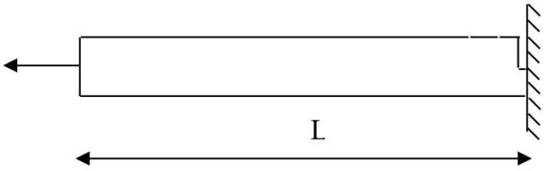
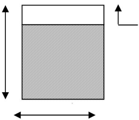
Table 1.
Material properties
| Material | Aluminum |
| Modulus of elasticity | 70 Gpa |
| Density | 2700 Kg/m |
| Poisson's ratio | 0.35 |
Considering a one-dimensional continuum media, Doyle (1997) [20] gives the equation of motion governing the longitudinal vibration of a uniform bar;
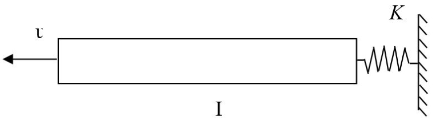
The transverse edge crack is modeled by a translational axial spring with stiffness as shown in Figure 3.
There are several expressions of spring stiffness that can be found in literature for the transverse vibration (Rizos et al. 1990) [21] and (Ostachowicz and Krawczuk, 1991) [22]. Ruotolo and Surace (2004) gave concerning the longitudinal vibration, the equivalent axial spring stiffness expression for double edge cracked bar [23] and by analogy to the bending vibration of an edge cracked beam, Sayyad et al (2013) [18] were the ones who developed expressions of axial spring for longitudinal vibration. In the next section based on the Castigliano’s theorem and the strain energy release rate for an edge-cracked bar, we determine the expression of axial spring.
Determination of the equivalent axial spring stiffness Kx
The longitudinal spring stiffness equivalent to the transverse edge crack is based on stress intensity factor and Castigliano’s theorem. Under a remote load, the additional displacement along the direction of a force due to the presence of the crack is determined using Castiglione’s theorem along with Paris equation (Tada et al., 2000) [24] and (Sih, 1973) [25].
If is the strain energy due to the crack; Castiglione’s theorem requires that the additional displacement is;
Along the force , the strain energy takes the following form (1) ;
where b is the bar thickness and Js the strain energy density function.
and is the stress intensity factor for fracture mode I.
Due to the stress , SIF in mode I is given by;
denotes the remote stress, a is the crack depth, h is the height of the element bar.
The local flexibility can be computed as follows;
The equivalent axial spring stiffness due to the crack can also be determined by the following formula;
where;
Frequency equation of a cracked cantilever beam
Rao (2007) [26] gives the solution of Eq. 1 for a free longitudinal vibration of a bar;
At the free end x = 0, we get;
Using both Eqs. 12 and 13 yields to;
Thus, Eq. 12 reduces to;
The boundary condition at x = L can be expressed as;
Substitution of Eqs.17 and 18 leads to the following expression;
Introducing the mass of the bar as;
Eq. 17 can be rewritten under the form;
where ; is the frequency parameter for both uncracked and cracked bar;
By neglecting the higher order values in Eq. 11, Eq.22 becomes;
For a limited development of characteristics Eq. 24, can be written;
In order to determine the influence of the higher order terms of Eq. 25 on the response frequency of a cracked cantilever bar, the equation is solved for considering 1, 2 and 3 higher order terms. Solutions for these last three cases are compared with the solution given by Eq. 24.
Case 1: One higher order term of Eq. 25;
Thus, Eq. 24 can be written as;
Case 2: Two higher order terms of Eq. 25:
Then, Eq. 24 can be written as;
After simplification Eq. 29 can be written as;
Eq.30 becomes;
The solution of this equation is given by;
Thus, the following equation is obtained;
Case 3: Three higher order terms of Eq. 25:
Ignoring higher order term of Eq. 25, the frequency Eq. 25 can be rewritten as follows;
Let, then Eq. 36 becomes;
Eq. 37 is a third-degree equation of the form:
Solution to this equation is obtained as follows;
where;
Substitution of Eqs.39 and 40 into Eqs. 41 and 42, respectively, we obtained;
Solution of Eq.38 is given as follows;
The frequency parameter can be expressed as;
The fundamental frequency can be computed by the following equation:
where;
Values of frequency corresponding to the first mode for longitudinal vibration of an uncracked cantilever bar are summarized in Table 2.
Table 2.
Value of λ for uncracked bar (a/h=0)
| Eq. 28 | Eq.35 | Approximate Analytical solution Eq. 47 | Numerical solution of Eq. 24 | |
| λ | 1.732 | 1.601 | 1.578 | 1.571 |
It can be seen from Table 1 that the proposed approach can easily give the value of the frequency parameter λ for an uncracked bar (a/h = 0). The accuracy of the approximate solution depends mainly on the terms of higher order considered for calculation. It is noticed that the accuracy value of λ is obtained when one considers for the calculation three terms of higher order (Eq.47).
Results interpretation
Numerical example
A cracked cantilever bar under free longitudinal vibration is analyzed. The crack is located near the clamped end of the bar. The dimensions of the bar are 0.22 m x 0.0254 m x 0.01 m, the material properties are given in Table 2. The effect of the terms of higher order on the fundamental mode shape of vibration for both uncracked and cracked bars are studied (see Figures 4 and 5), while effects of crack depth ratio on the fundamental longitudinal frequency for a cracked cantilever bar are presented in Table 3 and shown in Figure 6.
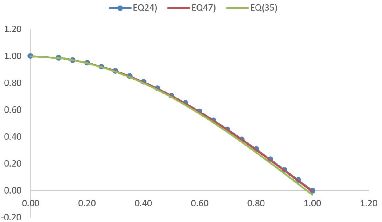
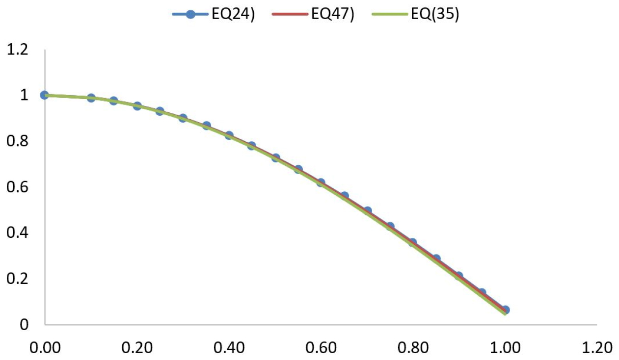
Table 3.
Values of First longitudinal frequency (Hz) for different crack depth ratio
| a/h | Β | Approximate Analytical solution (Eq.47) | Numerical solution of equation.24 | Error % |
| 0.0 | 0,0000 | 5923,517 | 5896,114 | -0,46 |
| 0.1 | 0,0040 | 5912,255 | 5885,978 | -0,45 |
| 0.2 | 0,0160 | 5882,225 | 5857,825 | -0,42 |
| 0.3 | 0,0359 | 5833,425 | 5809,025 | -0,42 |
| 0.4 | 0,0638 | 5762,103 | 5739,580 | -0,39 |
| 0.5 | 0,0997 | 5668,257 | 5647,611 | -0,37 |
| 0.6 | 0,1436 | 5548,135 | 5531,618 | -0,30 |
Effect of high terms of frequency on the mode shape for a cracked bar
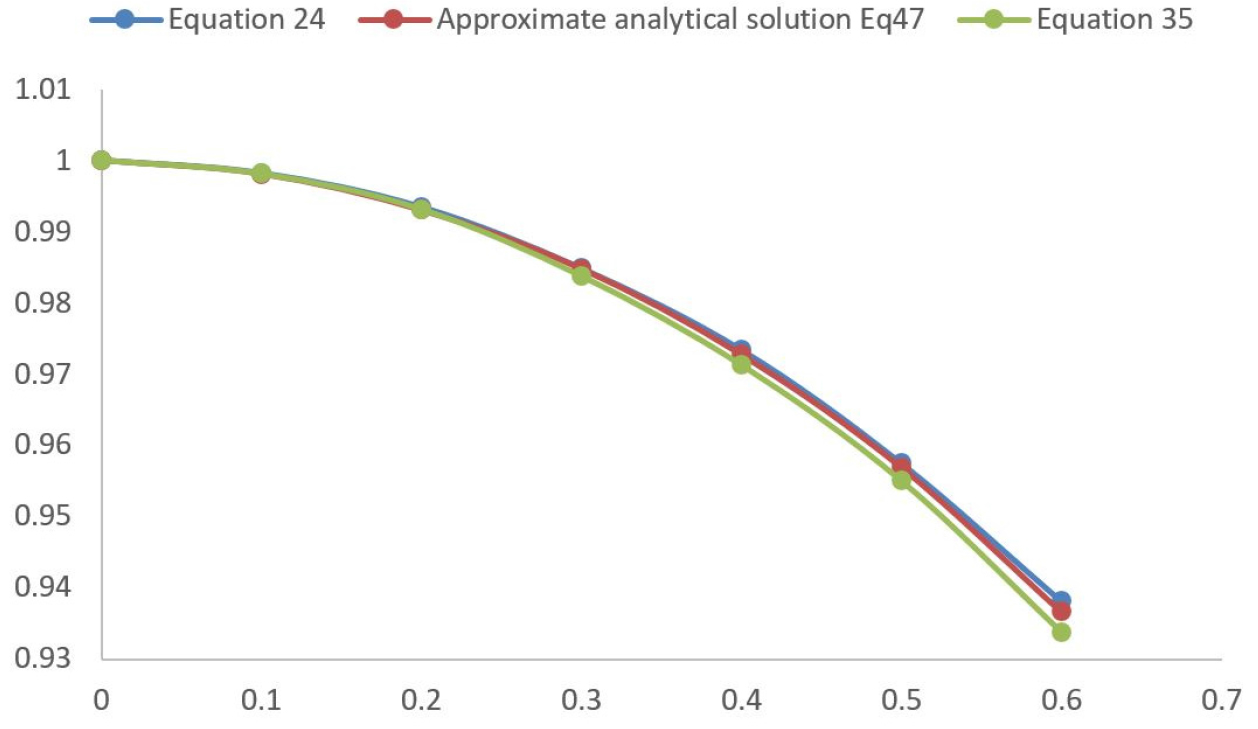
In order to determine the influence the high order terms of the frequency parameter on the fundamental longitudinal mode shape; Figures 4 and 5 shows the modes shapes for an uncracked and a cracked cantilever bar obtained by the both approximate analytical solution (Eqs. 35 and 47) and numerical solution of analytical equation (Eq. 24). It is observed that the three curves are almost identical either in the case of the cracked bar (a/h = 0.5) or the case of the intact bar (a/h = 0).
Determination of the longitudinal frequency of a cantilever cracked bar
Longitudinal natural frequencies of the cracked bar for the first mode of vibration have been studied and are given in Table 3.
Figure 6 shows the fundamental normalized longitudinal frequencies (w/w0) determined by the approximate analytical solution (Eqs. 35 and Eq47) and also by the numerical solution (Eq. 24) for different crack depth ratios (a/h). It can be seen that the estimated values of the first longitudinal frequency of the cracked cantilever bar are very close to those calculated from the analytical solution. The crack is modeled by a longitudinal spring. According to Eq. (11), it is noticed that when the crack depth ratio increases, normalized longitudinal frequencies of a cracked cantilever bar (w/w0) decreases. In this case, the spring stiffness undergoes the same reduction and involves a reduction in the stiffness of the cracked bar. On the other hand, the proposed approach gives values of the first longitudinal frequency for different crack depth ratios which differ only by about -0.47% from those calculated from the numerical solution of the analytical solution.
Mode shapes analysis of a cracked cantilever bar
The modes shapes for longitudinal vibration of cracked and uncracked cantilever bar are presented and compared in Figures 7, 8, 9.
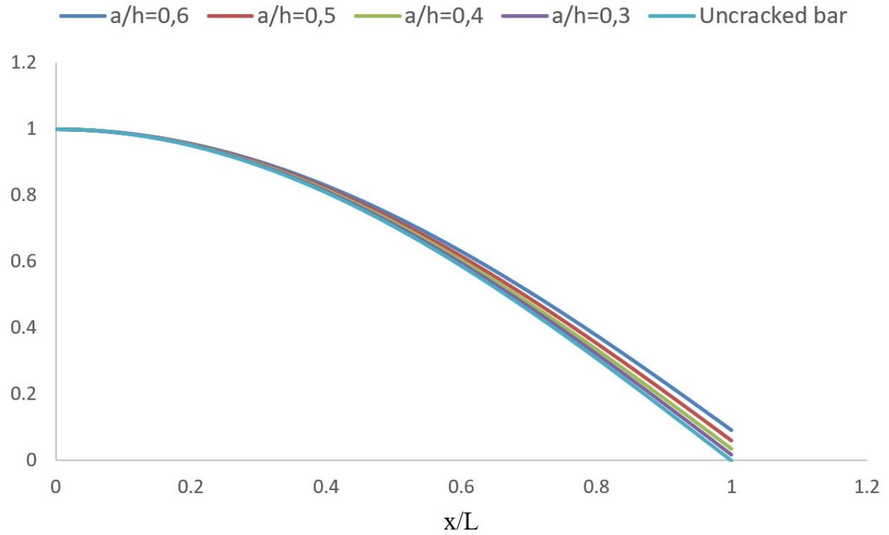
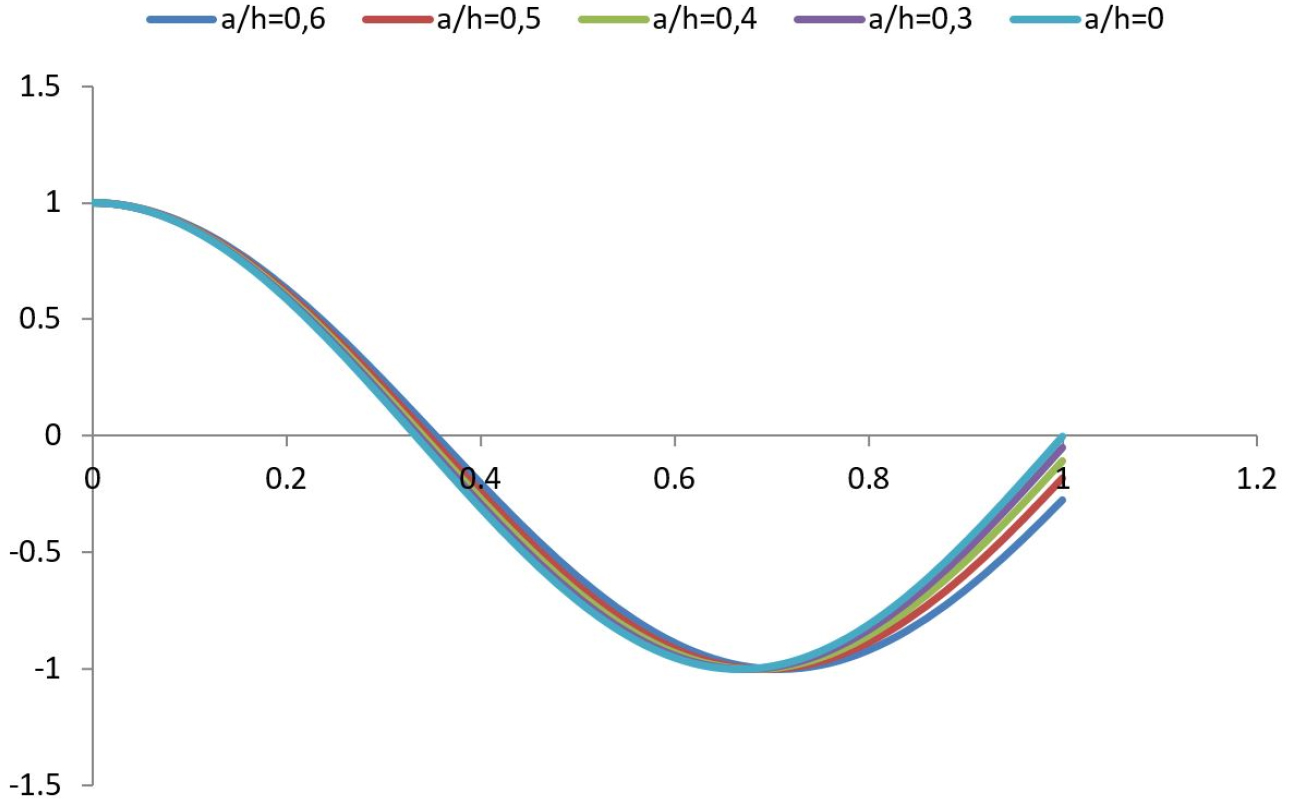
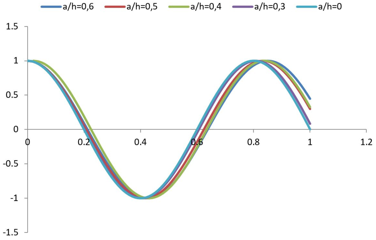
Figure 7 presents the influence of the crack depth ratio on the fundamental longitudinal mode shape for cracked cantilever bar which the frequency parameter λ is calculated by the approximate analytical approach. The results indicate that there is a deviation for the first mode shapes of the cantilever cracked bar compared with those of the uncracked bar. It is observed that this deviation increases with an increase of the crack depth ratio. For this case, different crack depth ratio (a/h = 0 to a/h = 0.6) are considered. For a crack depth ratio a/h < 0.3, small changes in mode shapes of a cracked cantilever bar are noticed and for a crack depth ratio (0.3 > a/h < 0.6), the longitudinal mode shape of a cracked cantilever bar undergoes changes.
Figures 8 and 9 show the second and the third mode shape of a cracked and an uncracked beam, respectively. It can be noticed from these figures the deviation between a cracked and an uncracked beam at the position of the crack increases with an increase in the mode of vibration. It is found that for all mode shapes, the difference between the mode shapes of a cracked and an uncracked beam is always sharply changed at the crack position with a depth ratio a/h greater than 0.3.
Conclusion
In this research work, the fundamental longitudinal natural frequencies and mode shapes of a cantilever bar with a crack near at clamped end are analyzed. A frequency equation corresponding to this particular problem is obtained and developed in series of terms, neglecting higher order terms. This equation is converted into a third degree equation. The solution for this last gives an expression of the fundamental longitudinal frequency of a cracked cantilever bar. The influence of different crack’s depths ratio on the normalized longitudinal natural frequencies and mode shapes of a cracked cantilever bar has been shown. It is found that the increase in the crack depth ratio involves a decrease in the normalized fundamental longitudinal frequency. It is also shown in this study that this approach for a cantilever cracked bar by the approximate analytical approach is suitable and useful in the determination of the fundamental longitudinal frequency. Obtained results are very close to those determined by the numerical solution from the analytical equation.
