

Introduction
Material and Methodology
Ferrochrome slag
Environmental acceptance of the use of ferrochrome slag under foundations
Reinforcement
Setup of the model footing test
Result and Discussions
Bearing capacity of unreinforced ferrochrome slag
Bearing capacity of reinforced ferrochrome slag with multi-layers of geotextile (nonwoven)
Bearing capacity of reinforced ferrochrome slag with multi-layers of geogrid
Effect of the footing shape on the reinforced ferrochrome slag bed
Bearing capacity ratios (BCR)
Conclusions
Introduction
The environment is under great pressure as a result of the continuous consumption of its natural resources by the various economic sectors, as well as the attempt to contain the resulting waste, which represents a real challenge that necessitates the search for sustainable alternatives to meet the increasing growth for these resources, in addition to finding effective solutions for the safe disposal of these wastes and by-products. India alone produces more than nine hundred million tons of waste annually, of which nearly three hundred million tons are industrial waste [1], and these numbers are increasing annually at the global level, due to the increase in industrial production that accompanies economic growth.
In response to this pressure, researchers’ attention turned towards studying the employment of industrial waste as an alternative to natural resources in several sectors, and its use has recently gained wide popularity in the construction sector, where many industrial wastes have been invested such as fly ash and copper slag in cement mixture [2, 3], crusher dust, fly ash and copper slag in paving layers and blocks [4, 5, 6], crusher dust, fly ash, copper slag, and blast furnace slag as an alternative to base materials [7, 8, 9, 10], but ferrochrome slag did not take a sufficient study to invest as a sustainable alternative material under the foundations, as it was only mentioned in very few studies [11], despite its distinctive properties that qualify it to be a good alternative to the granular natural resources under the foundations [12, 13]. This type of slag is a secondary product for the manufacture of ferrochromium alloys in blast furnaces [14, 15]. The global production of ferrochromium, according to 2017 statistics, amounted to more than 11.5 million tons, and this production is increasing at an annual rate of 3.8%, South Africa, Kazakhstan and India are controlling more than 82% of this production [16]. These alloys yield ferrochrome slag, which is estimated to be at least 1.1 tons per ton of ferrochromium, and it can be more depending on the associated mixtures [17], this slag is considered a waste that has so far only been invested in road paving [18] or used as a partial substitute for the aggregates in the cement mixture [19], these applications keep the usage of this slag to modest amounts.
The researchers’ journey began with the notion of reinforcement by putting metal tapes into the soil mass and evaluating them inside laboratory model tests [20, 21, 22, 23], therefore the concept of soil reinforcement is regarded as old and not a creation of recent decades. As there was a notable improvement in the carrying capacity of the soil, the pace of these studies intensified, thus it expanded to the inclusion of the ground reinforcement materials (geosynthetics) [24, 25, 26, 27], and predominantly sand was employed as a foundation soil because of the possibility of interlocking its grains with these materials [23, 24, 25, 26], where researchers investigated several important variables of this inclusion that directly affect the desired improvement results, such as the shape of the studied foundation, the relative density of the foundation soil, the number of layers of reinforcing material, the spacing between them, the depth of the first layer, and many other parameters that researchers seek to study and provide reliable results about them [27, 28, 29, 30, 31, 32, 33].
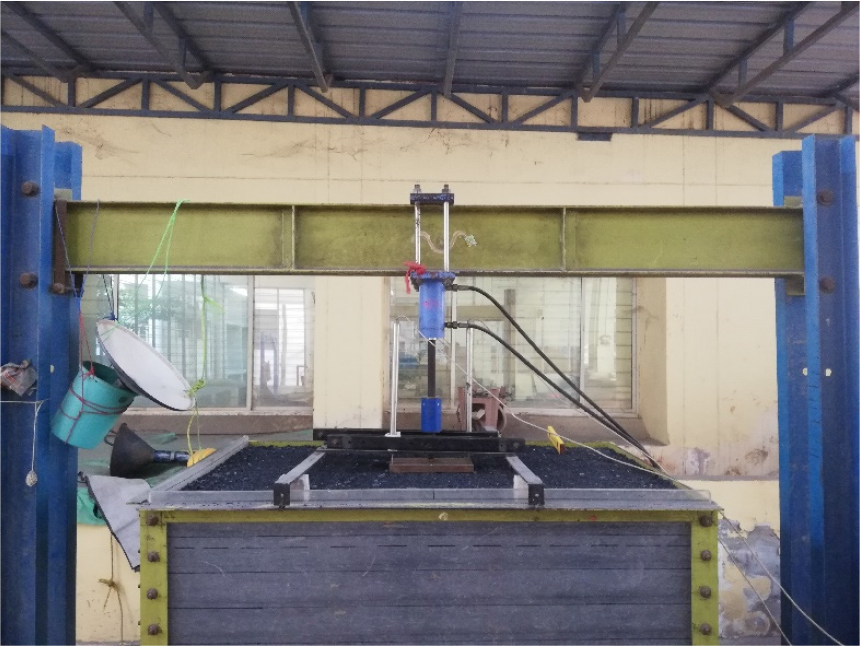
This paper seeks to study the behavior of ferrochrome slag as a sustainable material under two types of foundations, rectangular and square, with a medium relative density of 65%, and the effect of two types of ground reinforcement materials, geogrid and geotextile (nonwoven), to determine the resulting improvement in the bearing capacity, laboratory loading model tests were used to evaluate this behavior experimentally with and without reinforcement, Figure 1 shows a front view of the laboratory model equipment used.
Material and Methodology
Ferrochrome slag
According to the cooling ways, ferrochrome slag is formed in granular and coarse shapes. The granular type is produced as a result of cooling by water and has a size smaller than 6 mm and dark black color with sharp corners and a rough texture, whereas the coarse pattern is produced by cooling by air and is grey in color and larger than 2.5 cm, it has a finer texture and rounded edges than the grain pattern, Figure 2 in its parts (a) and (b) depicts the distinction between the two types in the shape.

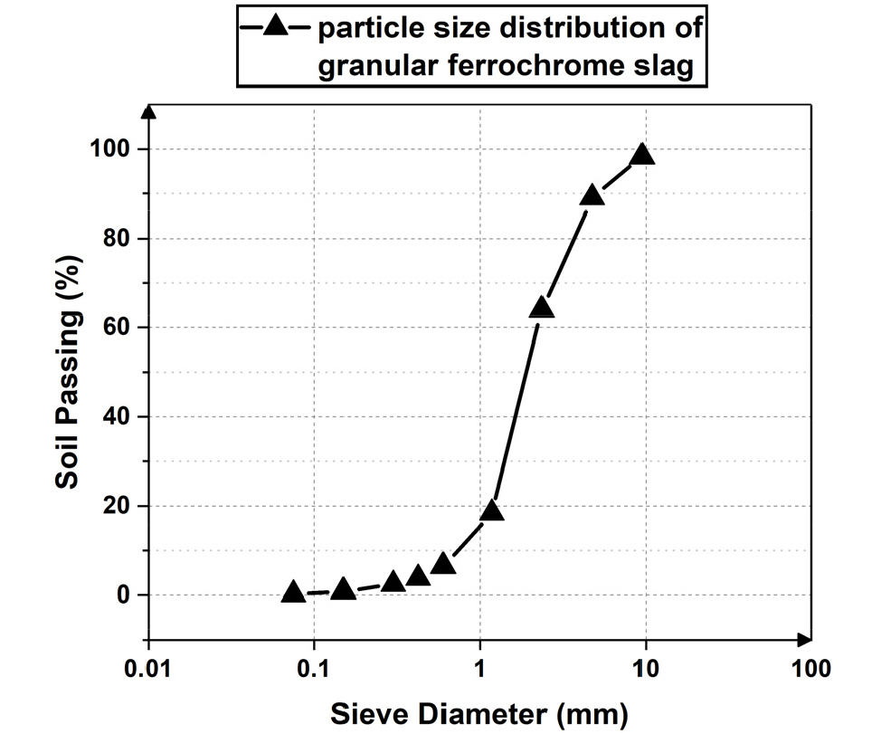
The ferrochrome slag used in this paper is granular and was obtained from an iron-chromium alloy factory in Odisha, India. This slag’s mechanical and physical properties were tested in the laboratory according to the American code (ASTM). The effective size of its particles (D50), coefficient of uniformity (Cu), and coefficient of curvature (Cc) was determined, according to ASTM D2487 [34], to be 1.85, 2.75, and 1.27, respectively, and its categorization is SP, Figure 3 shows the particles size distribution of this slag. According to ASTM D4253 [35], the maximum and minimum densities were determined to be 18.78 kN/m3 and 14.14 kN/m3, respectively. Depending on ASTM D854 [36], the specific gravity was measured at 2.944. The direct shear test determined the friction angle [37], and at a relative density of 65%, it equals 43.5°.
Ferrochrome slag is classified as a by-product that accompanies the production of ferrochromium; therefore, investigation of its chemical composition is critical. The oxides of silicon, aluminum, and magnesium are this slag’s main components, which depend mainly on the type of ore used, other factors such as melting time and its accompanying materials, and oxygen pressure interfere in the formation of this composition [38, 39]. Based on the X-ray fluorescence (XRF) test, Table 1 summarizes the oxides that form the ferrochrome slag in this research and the percentages of each of them. The Ferrochrome slag was found to contain a high amount of MgO (26.01%), for which it is not being able to use in the cement mortar and concrete.
Table 1.
The oxides forming ferrochrome slag and the percentages of each of them through XRF
| The chemical formula of the oxide | Percentage in composition |
| SiO2 | 23.2% |
| Cr2O3 | 12.6% |
| FeO | 3.56% |
| CaO | 6.02% |
| MgO | 26.01% |
| Al2O3 | 26.65% |
Environmental acceptance of the use of ferrochrome slag under foundations
The usage of ferrochrome slag as a foundation material requires checking the percentage of leaching of the toxic elements that make up it, and whether it is within the permissible limits. For this purpose, a chemical toxicological leaching or TCLP analysis was performed on a sample of granular ferrochrome slag and, investigating the leaching resulting from the toxic elements in the composition of this slag was conducted, which are total chromium, trivalent chromium, hexavalent chromium, and manganese. Table 2 shows the results of this test and the limits allowed by the US Environmental Agency. It can be noted that the leaching of these toxic elements is much lower than the indicated limits, which gives the ferrochrome slag environmental acceptance in terms of its use under the foundations.
Table 2.
The results of the TCLP test and the permissible limits by US the Environmental Agency
Reinforcement
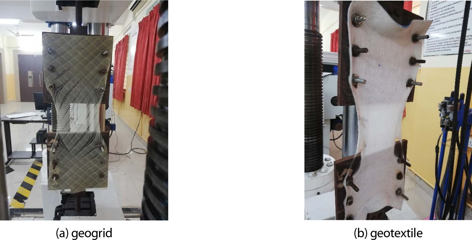
Geosynthetics materials include a wide range of synthetic materials, and they are commonly used in many civil engineering applications such as separation, filtration, drainage, reinforcement, etc.. For the purpose of strengthening the ferrochrome slag bed and studying the reinforcement effect on the bearing capacity, two types of these materials were chosen: geogrid and geotextile (nonwoven) to include inside the ferrochrome slag bed. The tensile strength of the reinforcement materials plays an important role in increasing the resultant improvement. According to ASTM D4595 [40], a tensile strength test was conducted on samples of the geogrid and geotextile, Figure 4 classifies the elongation-load plot for both of them, the maximum tensile strength value was 4.3 kN/m and 16.3 kN/m, respectively, these values correspond to previous studies [7, 41, 42, 43], and Figure 5 in its parts (a) and (b) shows a sample of geogrid and another one of geotextile after the tensile strength test finished. The thickness of the geotextile and geogrid layers was 2.3 mm and 0.5 mm, respectively. The mass per square meter was 300 g/m2 for the geotextile, and 20 g/m2 for the geogrid.

Setup of the model footing test
The Indian Standard for conducting the footing model test IS 1888-1962 states that the smallest dimension of the tank (or the pit) must be greater than or equal to five times the width of the foundation used in the experiment, allowing the failure area to have enough space to spread [44]. Accordingly, the used tank in this research was made from steel with dimensions 1.6 m ´ 1 m ´ 1.2 m (L ´ W ´ D). To prevent bending the footing plate during the loading, foundation models were manufactured of rigid steel with dimensions (150 mm ´ 150 mm) for the square footing, and (150 mm ´ 300 mm) for the rectangular footing. One of the most essential factors for the correctness of the results is achieving the researched relative density (65%) inside the test tank [45], for that reason, the raining technique was used to fill the tank, where the ferrochrome slag was poured into the tank through a metal funnel with a long mast, that ends with side openings to allow the material to exit from a previously determined considered height. This technique has been used by many researchers due to the good results it gave in achieving the required relative density [46, 47, 48, 49]. Load-settlement curves were drawn from values that were monitored through three digital indicators that transmit the changes from the load cell and two linear differential transformers (LVDTs).
To obtain the best optimization results for earth reinforcement materials, several researchers have investigated a set of parameters that directly affect these results, such as the depth of placing layers, the number of them, in addition to their width, tensile strength, and various other parameters. Some researchers have concluded that the best improvement result was when the first layer was positioned at 0.4B from the base of the foundation, and the best spacing between layers equals 0.3B, whereas they estimated the best width of a layer with five times the footing’s width [50]. These results were confirmed by others when they found that the width of the reinforcement layer can range from two to seven times the width of the foundation, and the number of layers can reach six layers depending on the response of the behavior of the footing material in increasing its bearing capacity [51]. Others gave a range between 0.3B and 0.4B as the first layer depth and the preferred layer width as 4B [52].
In this paper, the bearing capacity of a granular ferrochrome slag bed without reinforcement, and with one, two, and three layers of geogrid and geotextile were evaluated. The first layer was placed at a depth (u) of 0.4B, while the spacing between the rest of the layers (s) was 0.5B, and the width of layers (b) was equal to 5B. Figure 6 classifies a simple sketch of the model test, and Table 3 shows the details of the model experiment program in this research.

Result and Discussions
Bearing capacity of unreinforced ferrochrome slag
This stage of the footing model experiments is considered essential to recognize the foundation material’s bearing capacity before adding the reinforcement and the percentage of the improvement that occurred as a result of the reinforcement. The bearing capacity of unreinforced ferrochrome slag with medium relative density was evaluated under rectangular and square footings, and the intersection method of the tangent of the initial loading stage in the curve and the tangent of the final loading stage was used to obtain the bearing capacity. Experiments have been repeated several times to ensure their accuracy, and results that do not exceed 5-10% are taken.
Steel rigid plate was used as a rectangular foundation model according to the dimensions mentioned earlier (150 mm ´ 300 mm), Figure 7 clarifies two trials of the model test on the unreinforced ferrochrome slag, with a variation between them no more than 2%. By applying the intersection method, the bearing capacity under rectangular footing was determined to be 441 kN/m2. As a square model foundation, rigid plate with previously mentioned dimensions (150 mm ´ 150 mm). Figure 8 shows the load-settlement curve with an application of the tangent intersection method to determine the ultimate bearing capacity, which is estimated to be 432 kN/m2.

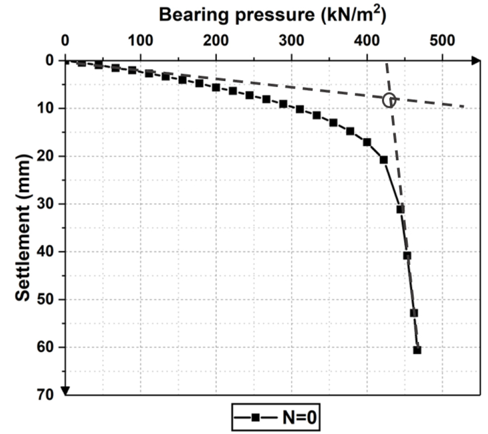
It was noticeable that in both types of footings, the failure mode was local shear, which corresponds to the failure pattern given by Vesic (1963) for the studied relative density in this paper [53]. By comparing the two values of the bearing capacity resulting from the square and the rectangular foundations, we can note the bearing capacity of the rectangle is greater than that of the square, which agrees with some studies [54], this observation may differ depending on the applicable loading conditions and the dimensions of each of the foundation model and tank (pit) used.
Bearing capacity of reinforced ferrochrome slag with multi-layers of geotextile (nonwoven)
In this stage, the influence of numerous layers of geotextile on the bearing capacity of the ferrochrome slag was examined, and the findings of this addition were demonstrated by testing under a square and rectangular foundation. The test was carried out by adding a layer, then two, and finally three.
Figure 9 shows the apparent increase due to the addition of several geotextile layers under a rectangular footing. The increase in the bearing capacity was 34%, 58%, and 95% as a consequence of adding one layer, two layers, and three layers, respectively. The semi-linear behavior becomes more pronounced as the number of layers increases, which is clearly shown in the load-settlement curve of three layers. The reason for this behavior can be attributed to the high elongation-load characteristic of this kind of reinforcement, which delays the appearance of a clear failure point.

The same behavior can be observed under the square footing, an increase in the bearing capacity with the increase in the number of layers of geotextile, and the appearance of a semi-linear curve with this increase. From the curves in Figure 10, the improvement in the bearing capacity due to single-layer can be determined as 41%, 58% for two layers, and 64% for three layers.

Bearing capacity of reinforced ferrochrome slag with multi-layers of geogrid
Geogrids are characterized by voids that allow the particles of the foundation material to permeate through them, allowing for more interlocking and thus an enhancement in the bearing capacity. In this part of the research, the effect of adding layers of geogrid to the granular ferrochrome slag bed was examined.
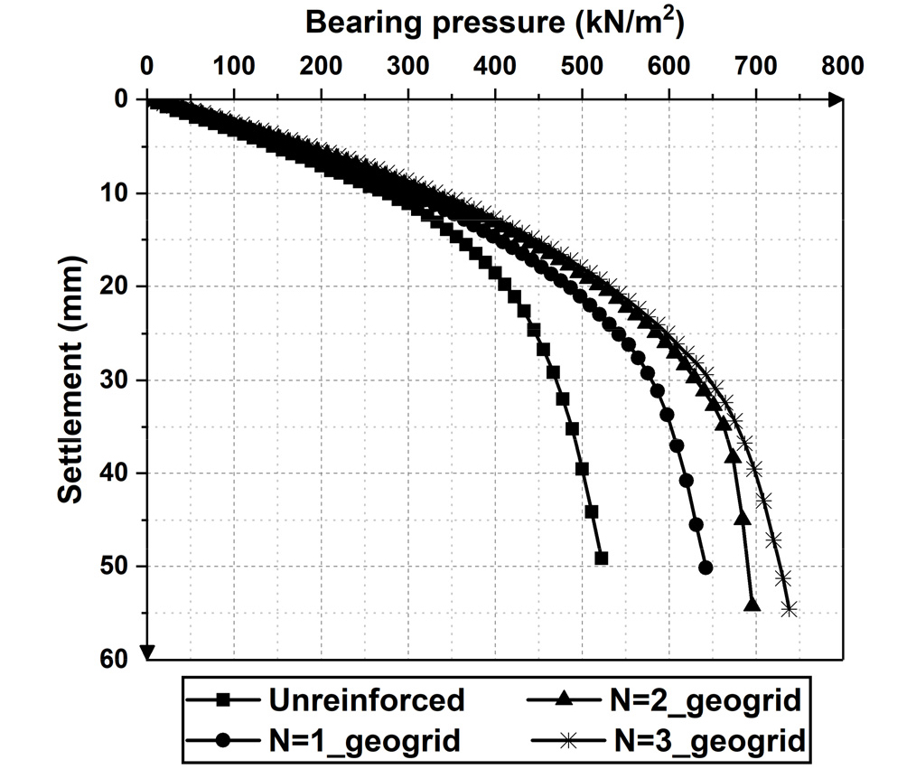
By analyzing Figure 11, it can be noticed that the bearing capacity under a rectangular foundation has improved by increasing the number of geogrid layers, where the increase was 25%, 45%, and 48% when adding one, two, and three layers. Through the same figure and the mentioned improvement values, it is observable that the performance of three layers is very close to that of two layers, and the enhancement is almost not noticeable.
On the other hand, Figure 12 shows the behavior of ferrochrome slag responding to the geogrid layers under a square foundation, and in contrast to the response under a rectangular foundation that is no longer mentioned after two layers, it continued to increase after the second layer, the increase in bearing capacity reached under a square foundation as a consequence of adding a single layer 7%, and 32% when adding double layers, and 52% as a result of adding three layers.

Effect of the footing shape on the reinforced ferrochrome slag bed
The variance in the improvement ratio differed between the rectangular and square foundations, as the ferrochrome slag improved with geotextile layers under the square foundation and showed better performance than that shown under the rectangular foundation in all cases of added layers. A portion of this performance shows in Figure 13 which shows a load-settlement curve of ferrochrome slag reinforced with a single layer of geotextile under square and rectangular foundations.
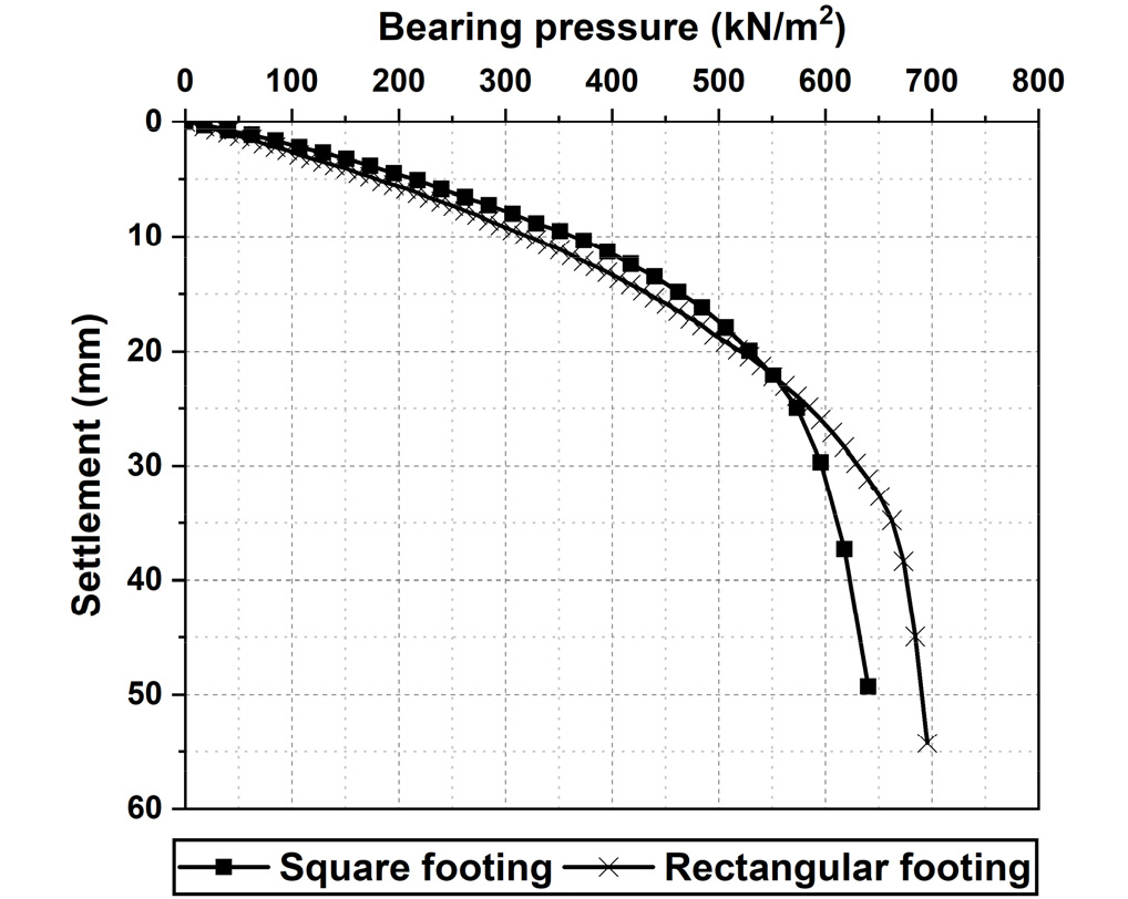
On the other hand, reinforced ferrochrome slag with layers of geogrid, in all cases of the different number of layers, showed close performance under square and rectangular footings until a certain settlement, then a better performance of the rectangle over its square counterpart after this settlement. Figure 14 shows this behavior of ferrochrome slag reinforced with two layers of geogrid under a square and rectangular foundation.

Bearing capacity ratios (BCR)
The term bearing capacity ratio is used to express the evaluation of the carrying capacity after adding layers of the reinforcement, Binquet and Lee are the first researchers who know and work with this term [21], this ratio can be calculated by finding the division of the value of the bearing capacity with reinforcement by the bearing capacity without reinforcement. By analyzing Figure 15, it can be observed that the bearing capacity ratio produced under a rectangular foundation as a result of using a layer and two layers of geogrid and geotextile is almost close, but it reaches a quantum leap when using three layers of geotextile, in contrast to the performance of three layers of geogrid, which did not show a great difference of the performance of the two geogrid layers.
In the case of a square foundation, Figure 16 shows a smooth increase in the bearing capacity ratio when using geotextile layers, and a semi-linear increase when using geogrid layers, but as in the observed behavior under a rectangular foundation, the use of geotextile layers gave an enhancement in the BCR higher than that given by the geogrid layers, Table 4 recaps the results of the model tests in this paper.


Table 4.
Summary of model test results for medium-density ferrochrome slag
Conclusions
A series of laboratory square and rectangular foundation model tests were carried out in this research to evaluate the behavior and bearing capacity of medium-density ferrochrome slag without reinforcement and with several layers of geotextile (nonwoven) and geogrid, in addition to chemical analysis and environmental acceptance checking to explore any damage that may be caused as a result of using it as foundation material, this paper concludes to:
(1) The results of the toxic leaching experiment of ferrochrome slag gave an environmental acceptance for its use as a base material for the footings.
(2) Through the tests of the rectangular and square foundation model, a good response can be detected in the ferrochrome slag bed and an improvement in its bearing capacity as a consequence of including the two types of ground reinforcement, geotextile and geogrid.
(3) The improvement results showed an increase of up to 45% in the bearing capacity of slag under a rectangular foundation when adding two layers of geogrid, but this increase became negligible when adding three layers, which indicates that any increase in the number of geogrid layers after two will not be beneficial.
(4) The improvement percentage in the bearing capacity of slag reached 95% under a rectangular foundation when adding three layers of geotextile, in contrast to the behavior of the geogrid, it showed a qualitative leap in the improvement percentage between two and three layers.
(5) The same response to the reinforcement can be observed under a square foundation, where the improvement percentage was 52% as a result of employing three layers of geogrid, and 64% as a result of employing three layers of geotextile.
(6) Geotextile-reinforced ferrochrome slag under a square foundation showed better performance than a rectangular one, while the performance was almost similar in the case of geogrid enhancement.
(7) Geotextile layers give greater reinforcement than those given by geogrid layers, as a result of their superior tensile strength over their last counterpart, in addition to the high elongation they show with increased loads.
