

Introduction
Background
Air Barrier System
Airleakage Rating Test
Building Description and Test Setup
Results and Recommendations
Conclusions
Introduction
Buildings play a substantial role in energy consumption, accounting for roughly 28% of worldwide greenhouse gas emissions [1]. The energy consumption of buildings is significantly influenced by space heating and cooling systems [2]. One factor contributing to the space thermal load within a building is the infiltration of air through its envelope components. Air infiltration can be accounted for an average of 33% of the heating loads for commercial buildings [3]. In a typical detached residential building, infiltration contributes to up to 30% of the energy consumption for space heating [4]. Air leakage typically refers to the unintended and uncontrolled air infiltration through building envelope components [5]. Air leakage commonly takes place at the interfaces and penetrations of building envelope components, such as mechanical and electrical penetrations, where the continuity of the air barrier system is disrupted [6].
Air movement within buildings is generated through pressure differences resulting from stack effect, mechanical ventilation systems, and wind. Consequently, these forces collaborate to establish a multifaceted and dynamically evolving pressure configuration within the building envelope [7]. The stack effect, commonly referred to as the chimney effect, occurs when air flows into and out of buildings through opening and penetrations due to the natural buoyancy of air. This buoyancy arises from disparities in temperature, leading to variations in air density between the interior and exterior environments. As a result, either a positive or negative buoyancy force is generated, driving the airflow. The intensity of the stack effect is determined by the magnitude of the thermal difference and the height of the structure, with greater temperature contrasts and taller buildings yielding stronger buoyancy forces and a more pronounced stack effect [8]. When a balanced ventilation system is installed, its impact on infiltration is minimal as it does not significantly alter the pressure differentials across the building’s leaks. This means that the total ventilation rate is simply the sum of the balanced fan flow and the natural infiltration, without any substantial changes, in contrast, unbalanced mechanical ventilation systems have a different effect on the indoor pressure of the building [9]. This modified indoor pressure resulting in airflow. In the case of exhaust fans, they create a depressurization effect within the building, leading to increased airflow entering through the building envelope. The greater the fan flow, the larger the proportion of the building envelope that experiences inward airflow. On the other hand, supply-only systems have the opposite effect, where airflow is directed out of the building due to pressurization. The movement of air surrounding a building generates wind pressure exerted on the structure. The magnitude, distribution, and characteristics of this pressure on the building envelope vary depending on the location. The intensity of the wind pressure is influenced by factors such as air density, wind speed, and the specific shape characteristics of the building [10]. The windward side of the building experiences positive pressure, creating a force that drives air into the building through its openings. Concurrently, negative pressure is generated on the leeward sides, resulting in the extraction of air from the building. This interplay of positive and negative pressures establishes a continuous airflow pattern, facilitating the exchange of air between the building’s interior and the external environment.
Airleakage also has negative impacts on indoor air quality and moisture condensation. In buildings where the envelope fails to achieve complete airtightness, significant air infiltration and exchange with the exterior environment occur, leading to higher levels of CO2, formaldehyde, radon, volatile organic compounds (VOCs), and respirable particles [11]. The leaky building envelope allows outdoor air, along with its associated pollutants, to freely enter the building, resulting in increased concentrations of these contaminants. This poses potential risks to occupant health and highlights the importance of addressing the envelope’s airtightness through improved sealing building envelop components. Another concern with unintentional airflow is the possibility of condensation occurring at supply air diffusers, air ducts, chilled water piping, air handling units, interior finishes, and structural elements [12]. When humid high vapour pressure air enters these components, it can come into contact with surfaces that are colder than the dew point temperature of the air, leading to condensation. This condensation can have detrimental effects, including microbial growth, corrosion, and damage to insulation materials. Therefore, designing and constructing airtight buildings is one of the primary goals of architects, building envelope consultants and developers.
Background
Air Barrier System
An air barrier system is an essential component of building envelope assemblies to minimize air leakage. The air barrier system is a group of materials that provide a continuous barrier preventing the unwanted exchange of air between the interior and exterior of a building. As discussed in the previous section, the primary purpose of an air barrier is to improve the energy efficiency of a building by reducing air leakage. When air leaks through the building envelope, it can result in energy losses, decreased indoor comfort and increased risk of moisture condensation.
To effectively serve as an air barrier, the material used must have a low air permeance, typically measured in liters per second per square meter (L/s/m2). To be recognized as an air barrier in Canadian Standards, the specified air permeance for the material should be less than 0.02 L/s/m2 when tested to ASTM E2178, “Standard Test Method for Air Permeance of Building Materials” [13]. Also, compliance with the CAN/ULC- S741 “Material Specification Standard” is required for air barrier materials [14]. The air barrier system consists of air barrier materials should demonstrate an air leakage rate of no more than 0.2 L/s/m2 when subjected to testing as per the ASTM E2357 “Standard Test Method for Determining Air Leakage of Air Barrier Assemblies” [15].
To serve as an air barrier system, all joints, laps, and penetrations in the air barrier system must be sealed to ensure continuity and prevent any gaps or openings that could allow air to pass through. This may involve the use of tapes, sealants, adhesives, or other appropriate methods to achieve an airtight seal. The air barrier must be structurally supported to withstand both positive and negative air pressures exerted on the building enclosure. It should also provide continuity across joints, between assemblies, around penetrations, and at material transitions.
Additionally, all joints, penetrations, and openings that contribute to the air barrier must be sealed using appropriate methods compatible with the construction materials and location. The seals forming part of the air barrier should be securely installed to ensure they do not dislodge, loosen, or compromise the ability of the air barrier to resist positive and negative air pressures exerted on the building enclosure. Moreover, all openings within the air pressure boundary must adhere to specific airtightness requirements. This includes fenestration such as windows and doors, which must meet the airtightness standards set by relevant energy and window regulations. Doors that are part of the air pressure boundary must also comply with energy standards, and if they are unable to meet these requirements, additional measures such as gaskets, weather stripping, and alternative seals must be employed to minimize air leakage. Furthermore, mechanical exhaust vents must be equipped with backdraft dampers, and electrical boxes and fixtures should be gasketed and sealed at all openings to ensure airtightness.
Airleakage Rating Test
Building air leakage is quantified by calculating the airflow rate. The measured airflow rate due to infiltration, indicated as Q (L/s), signifies the amount of air volume per unit of time needed to sustain a predetermined pressure difference across the air pressure boundary [16]. The normalized air leakage rate, represented as q (L/s/m2) is calculated by dividing the airflow Q at a specified pressure by the area of the pressure boundary.
One approved test method to calculate airleakage rate of a building is ASTM E779, “Standard Test Method for Determining Air Leakage Rate by Fan Pressurization” [17]. During the airtightness test procedure outlined in ASTM E779, several steps and considerations are specified. To create a uniform pressure within the air pressure boundary, all interconnecting doors should be open. Differential pressure measurements should be taken at the highest ceiling and lowest floor elevations on the windward and leeward sides to verify the uniform pressure condition. HVAC balancing dampers and registers should remain unadjusted, operable dampers should be closed. The building envelope is connected to the air ducts or other mechanical penetrations, and openings must be sealed to prevent air leakage. Zero flow envelope pressures must be measured with the fan opening blocked, and these values are subtracted from the envelope pressures measured during pressurization and depressurization. Applying air blower door fans, the induced pressure difference during the test ranges from 30 to 75 Pa. Incremental pressure differences of 5 Pa must be used, and airflow rates and pressure differences across the envelope must be measured at each pressure difference. Data is collected for both pressurization and depressurization. Commercial software is available that utilizes data collected from blower door fans to calculate the air leakage rate of a building. These software solutions provide the air leakage rate at specific pressure as an output, taking into account the measurements obtained during the testing process. The software inputs are building height, building envelope volume and area, elevation above sea level, wind speed and interior and exterior temperature. The number of required fans can be calculated based on geometry and volume of the building as per ASTM E779.
Nevertheless, air leakage testing is a relatively new concept in the North American construction industry, and there are still various aspects and challenges that remain to be explored and addressed. The field of air leakage testing is continuously evolving, and further research and advancements are needed to fully understand and overcome the current uncertainties and hurdles. In the upcoming section, a case study will be presented, focusing on the airtightness assessment of a retail building as per ASTM E779 and the measures taken to achieve the desired airtightness target. The case study will delve into the specific challenges faced, the evaluation of the air leakage, and the subsequent remediation steps implemented to address any identified issues. Through this case study, valuable insights and practical solutions will be shared, buildings and offering guidance for achieving optimal performance in terms of energy efficiency, occupant comfort, and overall building sustainability.
Building Description and Test Setup
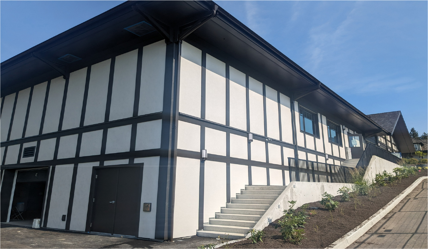
The building is a new construction one-story wood frame constructed over a concrete garage. The building is located in West Vancouver, British Columbia (Figure 1).
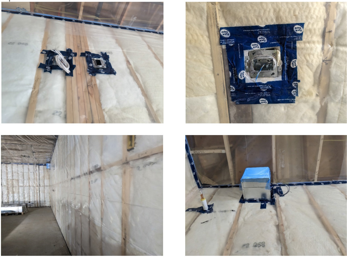
The wall air barrier system employed in the building consists of a 6mil polyethylene sheet on the interior and a permeable self-adhered membrane on the exterior. The polyethylene sheet, acting as the primary air barrier, is structurally supported and sealed at seams using acoustical sealant. Additionally, the polyethylene sheet is extended onto rough openings and sealed with acoustical sealant. To address electrical boxes, polybags were installed around them. Penetrations through the polyethylene sheet are sealed using air barrier tape and acoustical sealant. The polyethylene sheet is also sealed with acoustical sealant to the bottom plates and top plates and connected to a pre-strip of self-adhered membrane, creating a connection between the interior and exterior air barriers (Figure 2).
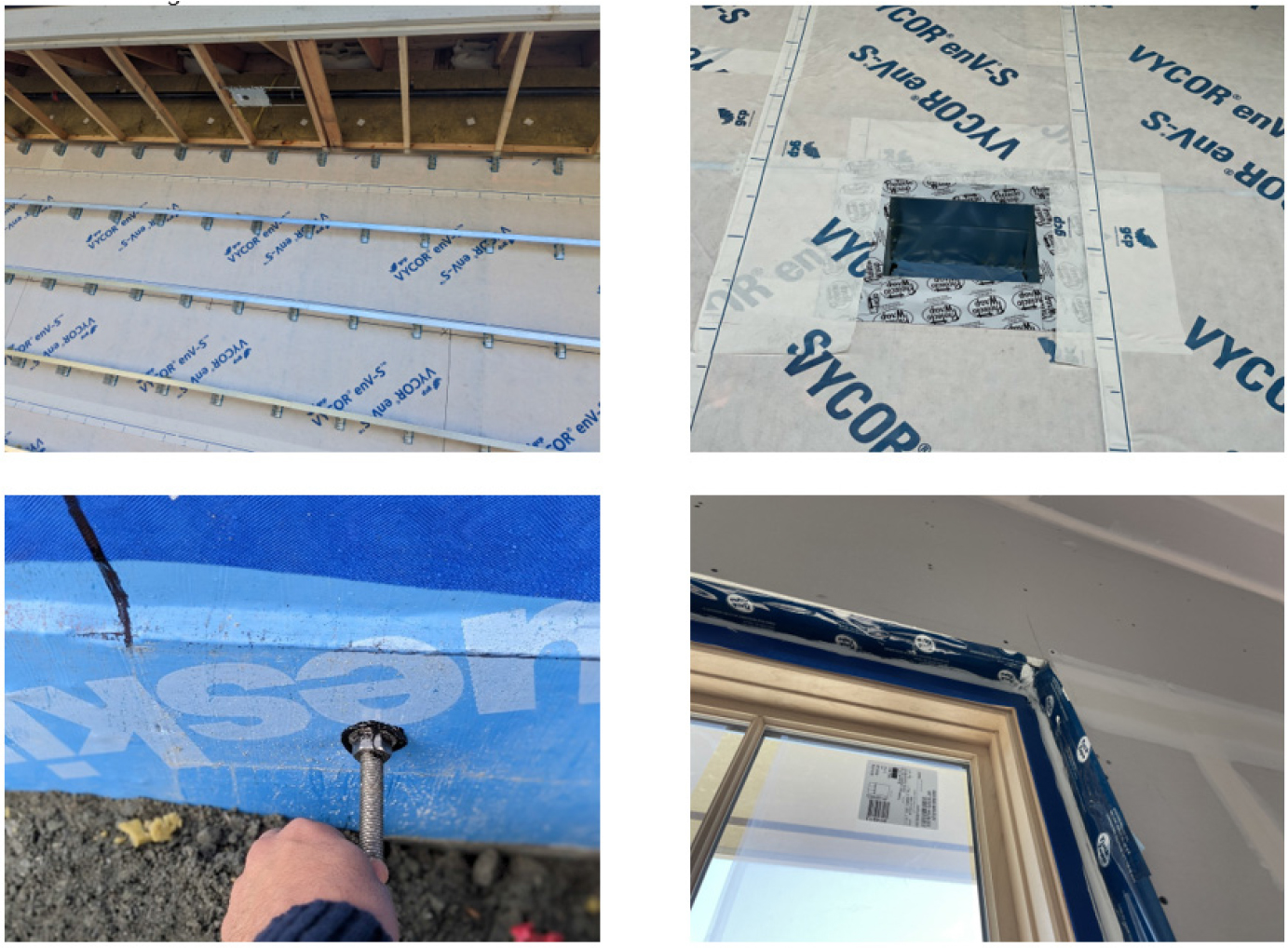
The wall’s exterior air barrier system incorporates a vapor-permeable self-adhered membrane, which is applied at the base of the wall and extended all the way up to the top plate.
To ensure continuity, sealant is installed around any penetrations through the self-adhered membrane. Moreover, the self-adhered membrane is extended onto rough openings and sealed onto the frames of windows and doors using backer rod and caulking, effectively creating an airtight seal. This comprehensive approach to the exterior air barrier system helps minimize air leakage and enhances the overall performance of the building envelope (Figure 3).
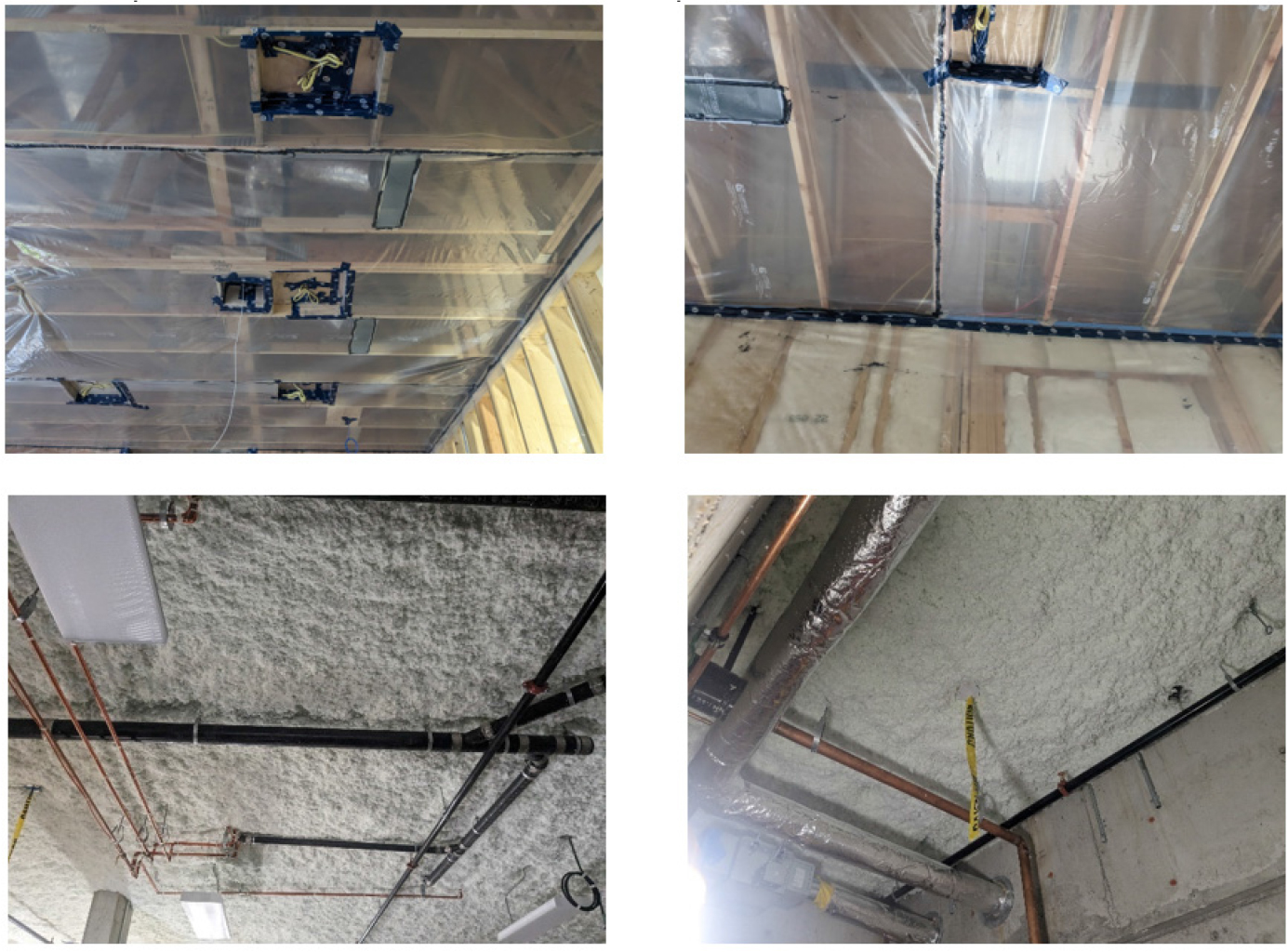
The ceiling air barrier system comprises a 6mil polyethylene sheet that is both structurally supported and sealed with acoustical sealant at the seams. To address potlights, polybags are installed around them and sealed using acoustical sealant and air barrier tape to the polyethylene sheet. Continuity is achieved by extending the polyethylene sheet onto the wall’s polyethylene sheet and sealing it with acoustical sealant, creating a continuous air barrier system.
Additionally, mechanical penetrations through the polyethylene sheet are sealed with acoustical sealant and air barrier tape to maintain the integrity of the air barrier. This approach ensures an effective ceiling air barrier. The floor air barrier system primarily relies on the concrete slab itself. Concrete is considered a superior air barrier material that can meet the air barrier requirements outlined in ASTM E2178. As a dense and solid material, concrete effectively restricts the passage of air, making it an inherent air barrier component within the building envelope (Figure 4). Building air barrier materials are listed in Table 1. The air permeability values were obtained from the manufacturers.
Table 1.
Building material properties
It should be noted that while doors are considered part of the air barrier system, their air permeability is typically higher than the requirements outlined in ASTM standards. This higher air permeability can make doors the weakest link in the chain of the air barrier system.
Due to their design and construction, doors often present challenges in achieving optimal airtightness. However, doors and Windows comply with airtightness requirements of North America Fenestration Standard [18].
The building preparation and test procedure were conducted as per ASTM E779 near the end of the construction when the air barrier system was installed completely. All mechanical penetrations and systems were turned OFF and sealed with polybag and tape. The intake and exhaust vents at the interior and exterior were also turned OFF and sealed with polybag and tape. All exterior windows were kept closed, and the air conditioning equipment was turned OFF. Interior doors were left open. The roof hatch was closed and latched. Exterior doors were kept closed. Plumbing traps were filled with water to ensure proper sealing and prevent the entry of air (Figure 5).
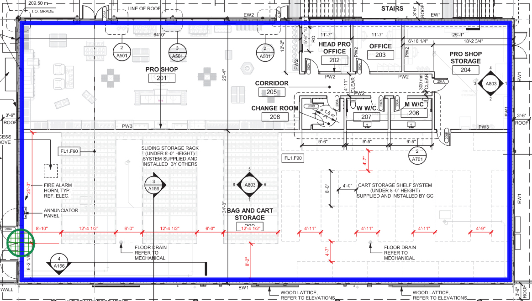
According to building geometry and airtightness target, the number of fans used for the test was calculated to a single fan. Figure 6 shows air pressure boundary or test zone with purple line as well as location sof below door fan with green circle on architectural plan. A pressure boundary, also known as a test zone, is defined as an area enclosed by an uninterrupted air barrier. To ensure accurate results, the pressure boundary should enclose a single zone, allowing for a relatively consistent pressure within the zone without significant variations [19]. Maintaining a consistent pressure within the test zone is important to evaluate the airtightness performance of the building or specific areas accurately. To create a single test zone, the blower door fan was located at a double door. This placement ensures that the fan effectively establishes the desired pressure boundary, encompassing the intended area for airtightness testing.
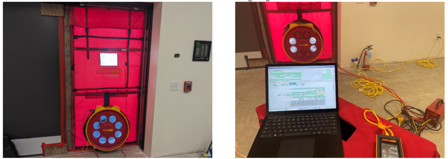
Retrotec 6000 blower door fan was used for this test. The testing system is designed to evaluate the airtightness of a diverse range of enclosures, spanning from highly leaky to exceptionally tight. It incorporates a powerful fan with six standard airflow ranges and an additional three optional low flow ranges, ensuring precise and reliable results across a wide variety of enclosure volumes. The system features the DM32X gauge, which enhances measurement accuracy and functionality [20]. The fan and the gauge both were calibrated by the manufacturer. Retrotec Fantastic Pro software was used along with the fan. The software provides a comprehensive solution for capturing and analyzing data obtained from fans and manometers employed in measuring air leakage within enclosures. When utilized in conjunction with Retrotec digital manometers, this software enables automated control of fans and facilitates data collection in accordance with various standardized air leakage testing procedures. It generates detailed reports that encompass both measured and calculated results, following the prescribed testing protocols. The software accommodates both automatically captured data and manual data input, ensuring accurate and comprehensive reporting of the testing outcomes [21]. (Figure 7).
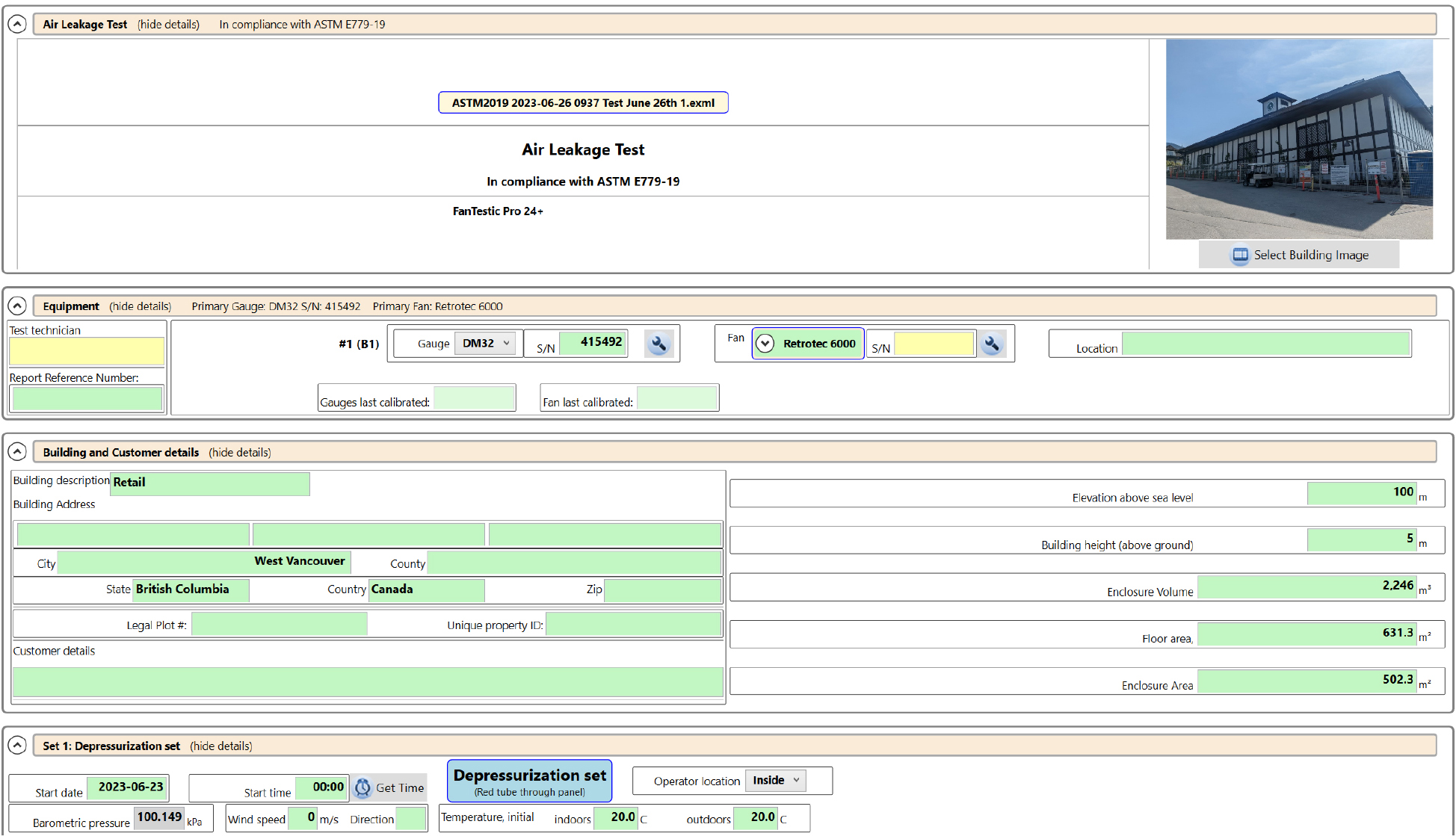
The Retrotec software is designed to accommodate various inputs, including building geometry calculations, as well as interior and exterior air conditions. These inputs play a crucial role in accurately assessing and analyzing air leakage within the building envelope. Figure 8 presents a screenshot showcasing the software’s user interface for inputting these parameters, providing a visual representation of how the software allows users to specify the necessary information for the analysis.
Results and Recommendations
The building has a specified airtightness target of 0.75 L/s/m2 at 75 Pa, which was determined by the project’s energy consultant. This target was established to ensure compliance with the energy performance requirements outlined in Step Code 2 of the British Columbia Building Code [22]. The test was performed following the ASTM E779 standard. The initial attempt did not meet the target of 0.95 L/s/m2 at 75 Pa, which was considered too high and failed to comply with the energy model requirements. The airleakage detection procedure was conducted as per ASTM E1186-22: “Standard Practices for Air Leakage Site Detection in Building Envelopes and Air Barrier Systems” Smoke Tracer Practice [23].
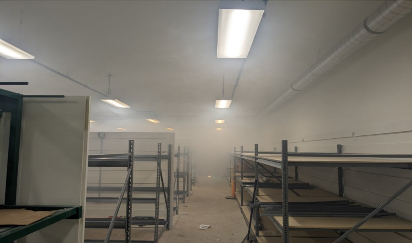
ASTM E1186 practice relies on the principle that when air passes through an air leakage area, it will either attract or redirect smoke that is in close proximity to the site. As a result, the area becomes visually detectable. Under normal operating conditions, pressure differentials across the building envelope occur due to variations in air density and wind. These differentials induce airflow through air leakage sites. Techniques such as building pressurization or depressurization can be employed to create enhanced unidirectional airflow through these sites, increasing the chances of smoke-seeded air being affected by the airflow. Once airflow is established in one direction through the air leakage area, achieved by pressurizing or depressurizing the building interior, a controlled source of smoke is brought close to the suspected air leakage site, and the direction of the smoke is carefully observed to discover the air leakage penetration through air barrier system. For this purpose, the building was pressurized to 75 Pa, and a smoke machine was utilized to track the path of air leakage (Figure 9).
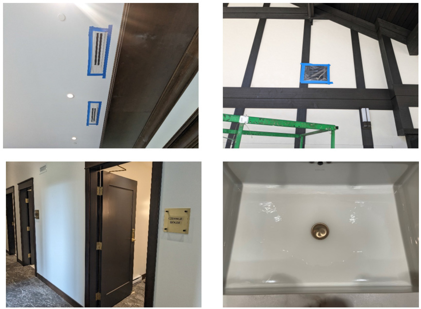
Upon tracing the source of smoke, we identified one significant path of air leakage, which was the sprinkler caps. After removing the caps, we discovered that the sprinkler heads had been installed through a polyethylene sheet without any proper sealing. It became evident that the contractor had cut the ceiling drywall after the installation and failed to seal the sprinkler heads correctly to the polyethylene sheet. To rectify this issue, we took the necessary steps for remediation. We promptly contacted the contractor and requested them to install acoustical sealant between the polyethylene sheet and the sprinkler heads. This solution was implemented for approximately six sprinkler heads that were affected. Following the remedial measures, we conducted another smoke detection test. This time, we observed that the air leakage at the previously problematic location had been significantly minimized. The installation of the acoustical sealant successfully addressed the issue and improved the overall integrity of the air barrier system (Figure 10).
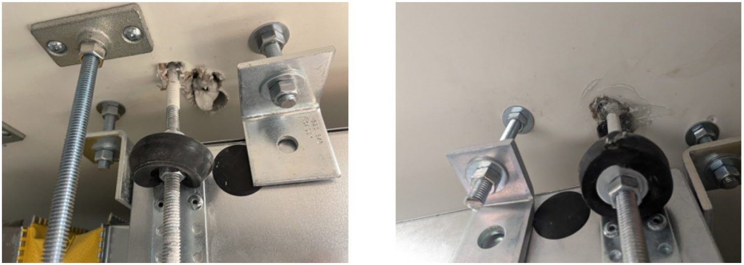
In addition to the aforementioned air leakage discovered at the sprinkler caps, we identified another problem area related to air infiltration. The issue was located around the fasteners that were supporting the HVAC units. These fasteners had been installed through the ceiling drywall, penetrating the polyethylene sheet without proper sealing. To resolve this issue, our instructions to the contractor included installing acoustical sealant from the polyethylene sheet to the fasteners, ensuring a proper seal. Furthermore, we asked them to fill the holes in the drywall around the fasteners with silicon sealant to provide an additional layer of protection against air leakage. Once the contractor completed these remediation tasks, we proceeded to conduct another smoke detection test. The results were encouraging as it became evident that the problematic area had been effectively addressed. The installation of the acoustical sealant from the polyethylene sheet to the fasteners, along with the silicon sealant in the drywall holes, contributed to minimizing air leakage in this specific location (Figure 11).
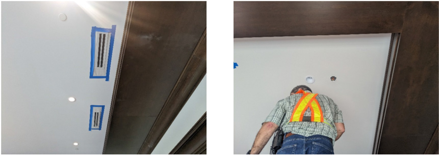
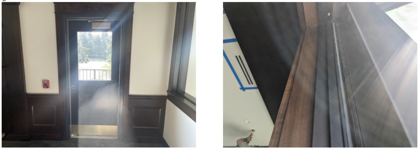
In addition to the previously identified air leakage areas, we also detected a path of air infiltration through the door. Upon inspection, we noticed that the door weather stripping had not been installed correctly, allowing daylight to be visible through the door sill. To rectify this issue, we instructed the contractor to adjust the weather stripping gasket. The objective was to ensure a proper seal and prevent any daylight from entering through the door sill. By addressing this specific area of concern, we aimed to minimize air leakage and maintain the integrity of the system. After the contractor completed the remediation work on the door weather stripping, we conducted another smoke detection test. This time, we observed a noticeable improvement, as the air leakage through the door sill had been significantly reduced. The adjustment of the weather stripping gasket proved to be an effective solution, mitigating the ingress of air and further enhancing the overall air tightness of the system (Figure 12).
After completing the remediation measures, we conducted another whole building air leakage test. This time, the measured value indicated an air leakage rate of 0.74 L/s/m2 (approximately 0.20 L/s/m2 lower than initial test), which fell within the acceptable range as defined in the energy model report. The successful remediation of the sprinkler caps, fasteners, and the door weather stripping played a significant role in addressing the identified air leakage points throughout the building. The combination of these remedial actions significantly minimized air infiltration, ensuring optimal performance and efficiency of the system. The measures taken to mitigate air leakage will contribute to improved temperature control, reduced energy consumption, and increased occupant comfort.
Overall, the diligent remediation efforts undertaken to rectify the air leakage issues have resulted in a more airtight and efficient building envelope. This accomplishment marks an important step towards achieving the desired performance goals and maintaining the desired indoor environmental quality. Table 2 summarizes the identified air leakage deficiencies and the corresponding remediation steps taken to address each issue.
Table 2.
Air leakage deficiencies and remediations
Conclusions
The study focused on air leakage testing of a new construction one-story wood frame building with a concrete garage located in West Vancouver, British Columbia. The building employed a comprehensive air barrier system consisting of polyethylene sheets, self-adhered membranes, and acoustical sealants to enhance airtightness. However, during the airtightness test, significant air leakage was detected, mainly attributed to punctures in the air barrier system after drywall installation. The remediation efforts addressed the identified issues, including sealing sprinkler caps, fasteners, and door weather stripping, resulting in improved airtightness and reduced air infiltration. These measures contribute to enhanced temperature control, energy efficiency, and occupant comfort.
In conclusion, our study highlights the crucial importance of conducting air barrier installation commissioning even after drywall installation. Our findings reveal that two out of three major air leakages were a result of punctures through the air barrier system post drywall installation. This emphasizes the need to ensure that the air barrier system remains undamaged throughout construction and occupancy phases. Merely installing an air barrier system is insufficient; builders and occupants must be trained to prevent any inadvertent damage to the system. We emphasize the significance of adhering to ASTM procedures for conducting tests and maintaining the integrity of the air barrier system.
