

Introduction
Demonstration Housing Project
Evaluation Parameters
Energy Performance
Durability
Ease in Construction and Maintenance contributing to Sustainability
Conclusions and Recommendations
Introduction
As per Census 2011, 31% of India’s population lived in urban areas and is expected to grow to 40% by 2030. This translates into a demand for around 10 million houses for which the Government of India (GoI), launched the Housing for All mission in 2015. The mission aims to demonstrate and deliver ready-to-live-in houses in minimum time and at minimum cost with high-quality construction. Though, construction of houses at this scale is an uphill task for which innovative alternative technologies from across the globe have been identified to enable a paradigm shift in the construction sector. One such technology is called the EPS core panel system which is faster, cost-effective, utilized a significant amount of industrial waste, and environmentally friendly than the conventional R.C.C. framed structure.
Research revealed the benefits of using EPS panels in buildings to reduce the environmental impact, cost savings, reduced energy consumption, faster construction, etc. [1, 2] advocated the role of EPS panels as an insulator to improve energy efficiency. [3] confirms the improved thermal performance achieved by using EPS panels in building envelopes. [4] underlined that the unit weight of EPS-embedded structure is up to 35% less than the conventional concrete structure. This is further corroborated by the research done by [5] that accentuates the cost savings achieved by using the EPS core panel system in place of the conventional R.C.C. framed structure with brick walls. The research further unfolds the reduction in foundation sizes, columns and beams sizes, and dead load of the structure by using the EPS core panel system.
Until now most research aimed to identify the feasibility and effectiveness of using the EPS core panels over the conventional system. The EPS core panel systems can be used for load-bearing structures up to Ground + 3 (G+3) stories as well as in R.C.C. framed structures as infill partitions. However, this study is limited to evaluating the EPS core panel system as an infill partition only. Various researchers highlighted the contribution of partitions type in achieving larger usable area i.e. carpet area, reduction in dead load, faster construction, and enhanced energy performance that all add up to cost savings [5, 6, 7, 8, 9, 10]. In addition, the sustainable aspects, i.e. CO2 emissions, embodied energy, durability, etc. are also important parameters that must be considered along with cost- related aspects for better decision-making [11]. Thus, this paper explores the indicators like 1) Energy Performance, 2) Embodied Energy (EE) and Carbon Content (CC), 3) Durability and 4) Ease in construction & maintenance contributing to sustainability.
Demonstration Housing Project
The site is located in Bhubaneswar and the constructed housing will cater to the Economically Weaker Section (EWS) categorized as low-cost housing. The housing project comprises 32 dwelling units, and the total no. of floors is 4 and each floor is having 8 no. of Dwelling Units (DU’s) (Figure 1). The overall built-up area is 1024 SqM. R.C.C. framed structure is used as a structural system whereas EPS panels are used as an infill material for walls (both external and internal) and floor slabs.

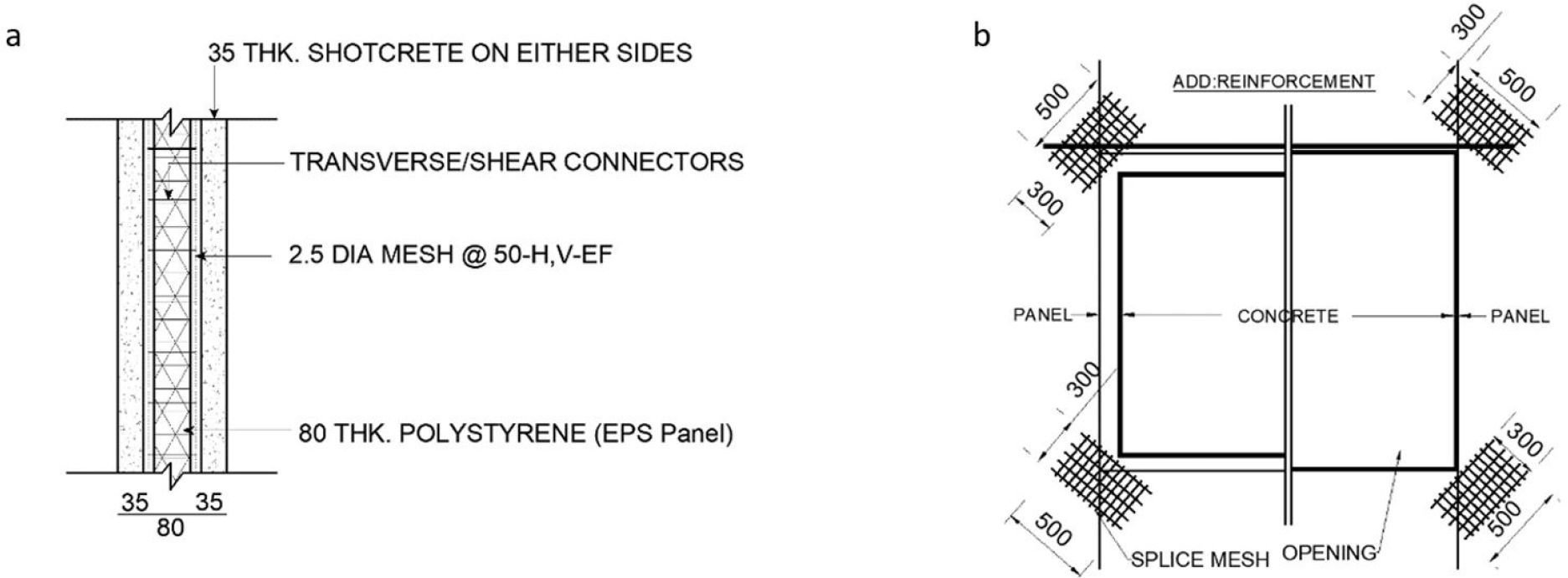
The construction of the project is based on the R.C.C framed structure supported over isolated and combined footings and completed with the EPS core panel (80 mm thick) with wire mesh (2.5 mm dia.) finished with 35 mm thick shotcrete on either side resulting in a total thickness of 130 mm (Figure 2a). The additional reinforcement is provided in the openings to support the frame (Figure 2b).
Evaluation Parameters
Energy Performance
This section presents an energy performance analysis and the impact of using the EPS core panel system instead of a traditional brick wall. For the analysis, three cases have been modelled (Table 1); the ‘Standard Design’ case represents a traditional building construction with brick walls, the ‘As Designed’ case represents the EPS core panel system, and the ‘Proposed Design’ case includes the recommended energy conservation measures (ECMs) for further improvements.
Table 1.
Summary of results
Figure 3 presents the impact of these measures in decreasing energy consumption in the building. Peak loads will be reduced by improving wall and roof thermal performance. Consequently, low energy demand and low energy consumption throughout the year.
Climate Analysis Methodology
For analysis, the weather data has been analyzed to identify periods of the year which fall out of the comfort zone. The annual Dry Bulb Temperature (DBT), Global Horizontal Radiation (GHR), and Diffuse Horizontal Radiation (DHR) are extracted from the Energy Plus Weather File (EPW) and plotted on the Climate Consultant v6.0. This tool plots the comfort temperature band as per the comfort equation from ASHRAE Standard 55-2004. The comfort band is based on ±2.50C tolerance over the annual monthly average comfort temperature. After plotting annual temperatures, direct and diffused solar radiation data, and comfort band, the periods where temperatures are beyond the comfort range have been identified. The psychometric analysis has been performed on Climate Consultant v6.0. This tool uses the weather data from the EPW file and the selected thermal comfort criteria. The Predicted Mean Vote model of ASHRAE Standard 55-2004 has been used. The tool plots the Psychometric chart and lists design strategies to improve thermal comfort.
Modelling Methodology
Building performance for all measures has been evaluated using HEED (Home Energy Efficient Design) software. This program evaluates energy consumption and peak demand on an hourly basis. Three cases have been modelled and simulated using this software.
∙Standard Design case: This model is based on space layouts and elevation design provided by the architect, and utilizes a traditional building envelope with a brick masonry wall and concrete roof slab.
∙As-Designed case: This model uses the design and envelope specifications proposed by the project team. (Expanded polystyrene core panel system)
∙Proposed Design case: This model includes higher performance windows with wood/vinyl frames proposed over the As Designed case.
The Standard Design case is modelled and evaluated for performance. This is followed by modelling and evaluation of the As Designed case. Based on the comparison of Standard and As Designed cases, Energy Computation Model (ECM) is prepared. The outcome of these iterations informs the selection of viable ECMs.
Energy Simulation Model Description
The model was prepared and simulated in HEED. It includes information critical for thermal Modelling. The space characterization based on which the model is prepared is considered consistent across all three cases and presented in Table 2.
Input parameters for the three cases that have been modelled are categorized into four sections that outline specifications for the building envelope (based on the wall sections as per drawings), sources of internal loads (lighting, equipment, and occupants), HVAC, and space usage as per NBC 2016. The thermal properties considered during energy modelling for Standard Design, As Designed and Proposed Design are presented in Table 3.
Table 2.
Area Summary
Table 3.
Thermal properties of building envelope components
Building Envelope Loads
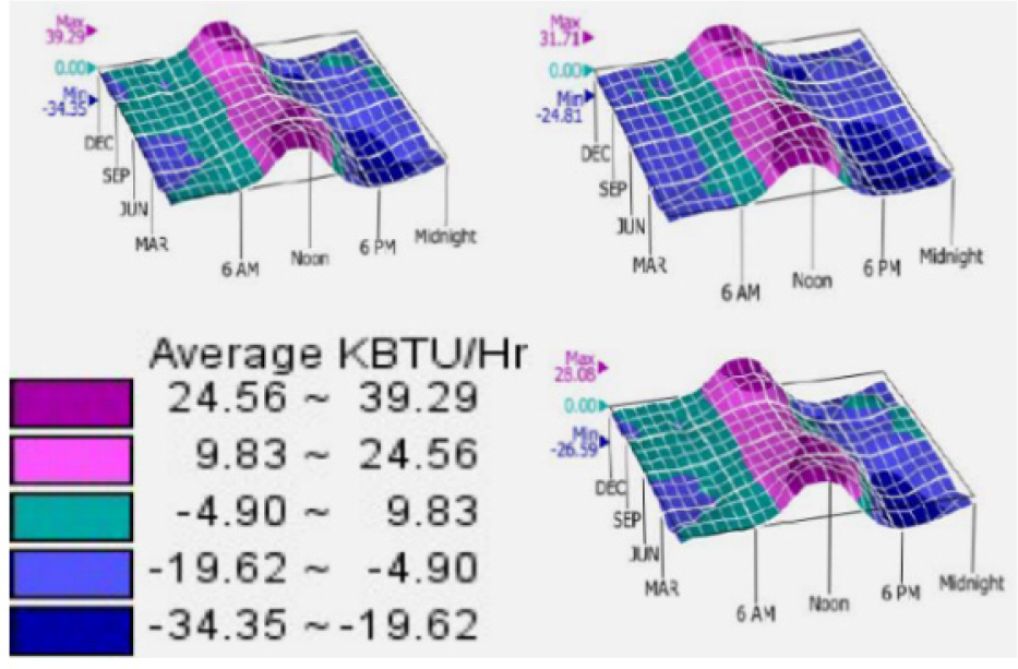
The annual peak load for the Standard Design case is 11.5 KW, for the As-Designed case is 9.3 KW, and for the Proposed Design case is 8.3 KW. Compared to the Standard Design case, the As-Designed case is 19.1% efficient and the Proposed Design case is 27.8% efficient. Furthermore, the envelope component load comparison highlights the impact of the EPS core panel, Heat gains are drastically reduced (Figure 4). Compared to the Standard Design case, the As Designed case roof and wall heat loads show 79% and 76% reduction respectively.

Building Envelope Indoor Temperatures
The energy model results indicate the EPS core wall-roof section helps in reducing indoor temperatures contributing to increased hours in the thermal comfort range. Figure 5 shows the comparison of annual indoor temperatures for standard design, as designed and proposed design. Table 1 presents the results obtained after the analysis.

Embodied energy (EE) and Carbon Content (CC)
The embodied energy of a material refers to the total energy required to produce that material, including the collection of raw materials. This includes the energy of the fuel used to power the harvesting or mining equipment, the processing equipment, and the transportation devices that move raw material to a processing facility. The greater a material’s embodied energy, the greater the amount of energy required to produce it, implying more severe ecological consequences. The embodied energy and CO2 emissions of the selected technology are calculated and then compared with the R.C.C. framed structure having clay bricks as infill material. Table 4 and Table 5 illustrate the comparison of embodied energy and carbon emissions of R.C.C framed structure with EPS infill panels for walls and roof slab vs R.C.C framed structure with brickwork and R.C.C for walls and roof slabs.
Table 4.
Comparison of EE and CC calculations for R.C.C framed structure with EPS and Brick wall as infill material
Table 5.
Comparison of EE and CC calculations for R.C.C framed structure with EPS infill panel and R.C.C for the floor slab
The EE and CC calculations are based on the coefficients taken from, Prof. Geoff Hammond and Craig Jones, Inventory of carbon and energy (ICE), Sustainable Energy Research Team (SERT), University of Bath.
For the studied project, ready-mix concrete is used from the plant located 25 Km; from the site. Similarly, the EPS panels are fabricated and transported from the plant located 200 Km away from the site, and Steel has transported from 50 km away from the site. Considering the truck used for transportation, the coefficients of embodied energy are taken from the research paper published by United Nations Centre for Human Settlements (Habitat) [12, 13]. For calculation purposes the coefficients of embodied energy for transportation are converted from MJ/Ton/Km to MJ/Kg/Km, similarly, the coefficients of carbon content for transportation are converted from KgCO2/12 Ton/Km to KgCO2/Kg/Km. Thus, Total Embodied Energy is the summation of Embodied Energy plus Embodied Transportation Energy; similarly, Total Carbon Content is the summation of Carbon Content plus Carbon Content of transportation.
In comparison, there is a substantial reduction in embodied energy and CO2 emissions of R.C.C framed structure with EPS as infill material. For the infill wall measuring 1m X 1m X 0.15m (EPS), the Embodied Energy and Carbon Content are found to be 3.04 and 3.05 times less than that of the same wall 230 mm thick of clay bricks. Similarly, while comparing the embodied energy and carbon content of the floor slab the figure comes out 1.17 and 1.43 times respectively.
Durability
From the durability aspect, the joints (i.e. wall to wall, wall to beam, wall to the column, etc.) are the vulnerable points to moisture. Thus, it is recommended to use chicken wire mesh at the joints before shotcreting. In case the joints are not treated with proper care during execution then, there are chances for the development of hair cracks which would be the entering source of moisture and may affect the durability in long run. The thickness of the walls is only 150 mm consisting of a 35mm thick layer of concrete on both sides and 80 mm EPS sandwiched between reinforced with 2.5 mm thick galvanized wire mesh. Although all the walls are non-structural members, there are high chances of damage in case of fire as the 35 mm concrete cover is insufficient to provide the recommended fire rating of (2hrs.) as recommended by National Building Code (NBC) for residential buildings. Thus, before implementing the technology on a mass scale, it is recommended to do laboratory testing of the structure to ensure the desired fire rating.
Ease in Construction and Maintenance contributing to Sustainability
Using pre-reinforced expanded polystyrene sheets will reduce the overall construction cost [5]. The assembly of these panels are simple and speedy as no special equipment is required for lifting/placing. The whole process of assembly doesn’t require any specialized skill set of workers. Henceforth, the duration of construction was reduced drastically due to the higher productivity resulting in savings in labour costs. Being lighter, these panels can also be assembled where the bearing capacity of soil is low as the dead weight of the superstructure is very less compared to that of conventional reinforced concrete structure hence it needs less strength for the foundation reducing the material cost.
While in conventional structures brick is used, in the case of the EPS external concrete layer is provided which prevents the attack of termites, insects, and rodents and provides a moisture barrier to the wall. As the EPS is impermeable it requires minimal long-term maintenance, especially in areas prone to extreme weather and temperature conditions summer heat, winter snow, heavy rains, and high wind. Thus, EPS is an affordable and incredibly sustainable choice throughout the industry due to its versatility and performance.
Conclusions and Recommendations
EPS core panel system positively contributes to the green-building approach of energy saving by reducing the amount of embodied energy, carbon emissions, and energy used for heating and cooling residential units.
The EPS technology showed flexibility to be used as an independent construction system or to combine with reinforced concrete skeleton systems and act as an isolated wall element. It reduces the foundation size (due to the reduction in dead load), thus saving material quantity due to its lightness in weight and reduced wall thickness resulting in achieving higher carpet area. The panels are customized based on design, however, restricted to any design changes on site. The consultants have to finalize the designs and shall provide clear shop drawings to facilitate the cutting at the manufacturing plant of the various wall or floor panels to appropriate sizes. In case of wall panels opening for doors, windows etc. shall be suitably marked in the respective panels. When the panels are to be cut at the factory in accordance with the cutting joints, these shall be suitably marked on the surfaces beforehand to facilitate correct identification for proper placement during erection at the construction site. Though these panels can be shaped at the site for creating simple fenestration elements i.e. sunshades, vertical and horizontal fins, etc. but for the decorative and complex elements the customized shapes of the panels are required to be ordered in advance.
Due to the thinner layer of shotcreting i.e. 35 mm on both sides, the holding capacity of these panels to bear the weight of heavy fixtures i.e. Air Conditioning Units, wall hangings, etc. needs to be evaluated and validated at the site. Hence, the customized hardware accessories i.e. bolts, fasteners, hangers etc. to support the installation of fixtures over these assembled panels must be innovated accordingly. As a new technology, there is little knowledge regarding repairing and retrofitting these structures due to the processes involved.
Through analysis, the EPS confirms the potential for better performance in terms of energy consumption and cost reduction. However, the technology requires testing over time. Advice from other stakeholders i.e., architects and building owners who are using this technology can assist in determining their long-range effectiveness.
Regular post-occupancy studies of buildings constructed using EPS technology on the parameters such as 1) Energy Performance, 2) Functional Failures or Defects, 3) Maintenance, and 4) User Comfort are recommended which can be extremely valuable in determining how well it functions and the ways for improvement in future designs and projects.
