

Introduction
Research Baseline
Geographical location and Climatic Characterization
Hypothetical Model Properties
Environmental Factors
Diagnosis
Solar Incursion
Natural Ventilation
Natural Lighting
Construction of the Tool
Application Example. Case Study Medellin
Solar Protection Criteria
Natural Ventilation Criteria
Daylight Criteria
Conclusions
Introduction
In the city of Medellin, Colombia, from the 1920s, the emerging industry and the rapid growth of the population, gave way to an urban expansion in the form of organic settlements, which subsequently led to a slow process of urbanization and legalization, which lack sustainability criteria. In the literature on bioclimatic architecture, studies indicate which is the ideal orientation of open facades according to climatic factors, the latitude, prevailing wind currents and availability of lighting resource (Olgyay, 2002). However, given the urban configuration of the city, in some cases it is not possible to choose the orientation of the open facades.
This research seeks to provide a tool for architects to design envelopes with bioclimatic criteria, according to the different orientations of open facades, assuming that any orientation can be imposed for a given site location. The importance of this tool lies in promoting and encouraging the construction of buildings designed with bioclimatic criteria that favor human well-being in inner spaces and decrease environmental impact by reducing the use of artificial climate systems, diminishing energy consumption in artificial lighting and optimizing building materials.
The research studied the behavior of a hypothetical model in eight different orientations, starting from the north and rotating 45° degrees each time to complete 360°, as illustrated in Figure 1.

A solar incursion, natural ventilation and natural lighting diagnosis was performed, and based on the results obtained in it, a tool that provides the architects with premises of passive design for building envelopes in 8 orientations was built. Finally, an example of application of the tool was made, in order to develop the envelope for a hypothetical model in two different orientations.
Research Baseline
The following parameters were chosen for analysis: geographical location and climatic characterization, properties of the hypothetical model and optimal ranges of environmental factors according to the architectural typology to be evaluated.
Geographical location and Climatic Characterization
The study was developed in the city of Medellin, Colombia, located in the Valley of Aburrá on the central Andes, at latitude 6°13'55''N and longitude 75° 34'05''O. Its temperature ranges between 12°C and 32°C having an annual average temperature of 22°C. The average relative humidity is 68% and the predominant wind direction is north (23%) - South (14%), with speeds between 1.5 m/s and 7.9 m/s (IDEAM, 1999a).
Hypothetical Model Properties
It was specified for this study, a hypothetical model of a rectangular shaped, 6m wide, 12m long and 3m high, located in a central block, whose areas of intervention are the main facade and the roof. The selected building typology was “office space”, as they are environments that require prolonged stay and in which complex activities with high requirements for sun protection, lighting and ventilation are developed.
Environmental Factors
Solar incursion:
To calculate solar incursion into the model, a solar chart for latitude 6.13°N was used. This graphical approach represents the positions of the sun in the sky and allows obtaining solar angles depending on the time of year and the time of day. This type of diagrams are easily obtained (Arquitectos, n.d.) or can be built (Bermudez, 1969).
The dates chosen for the diagnosis were December 21th and June 21th (solstices); and March 21th and September 21th (equinoxes). According to the spatial typology, it was determined that between 8: 00h and 16: 00h, direct sunlight should be avoided on the open facade.
Natural Lighting:
Daylighting simulations were performed with the Velux Daylight Visualizer 2.8 software, under partly cloudy conditions, on December 21th, June 21th and March / September 21th at 8: 00h, 12:00 and 16: 00h. This software, presents through a chromatic scale, the amount of luxes present in the space at the level of the work plane (0.75 m from the floor surface) in order to identify areas that are over-lit or poorly lit.
To define the permitted ranges and/or required lighting levels in office spaces, this study took as a reference the “technical regulation lighting and street lighting. RETILAP”(Ministerio DeMinasYEnergía, 2015). This document constitutes the lighting level standards which should by fulfill in each space, according to their type and activity. For office spaces, the lightning levels required on the work plane should be between 300 lx and 1.000 lx.
Natural ventilation:
To determine the size of openings necessary to naturally ventilate the space, “The Florida Solar Energy Centre Method 1” was used. This method calculates total opening area (TOA) required, considering an inlet and an outlet located in opposite facades, of equal area, and taking into account the effect of wind, regardless of the temperature. This formula was chosen as it proposed corrections to the wind direction and surroundings characteristics. It applies for one level buildings, if the block has several stories the formula should be applied individually for each of them.
Where TOA = total opening area in m2 (the sum of both the entry and the exit); V = volume of the building in m3; Ach = air exchanges per hour; W = wind speed in m/s; f1 = coefficient determined by wind angle of incidence; f2 = site correction factor; f3 = surroundings correction factor; f4 = height multiplication factor.
According to the chosen spatial typology, 10 Ach were considered as the minimum required and 30 Ach as the optimum air changes per hour (Tobar Arango, 2004).
Diagnosis
Once the parameters were stablished, a diagnostic analysis was performed to evaluate the behavior of the model in the 8 established orientations assuming the main facade is entirely open.
Solar Incursion
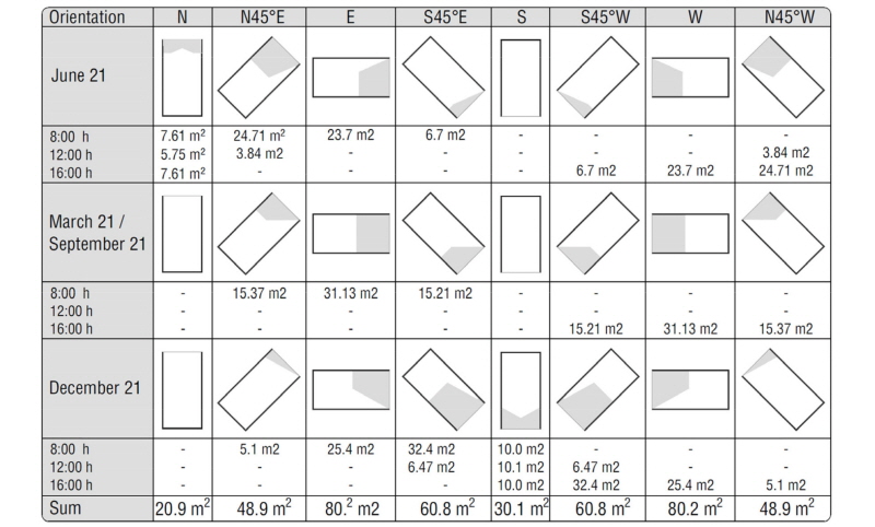
Based on the criteria established in the research base line, a solar incursion analysis was conducted for each orientation. In Figure 2, the areas on the floor that receive sun during the set dates and times, are indicated. In the columns, the orientation of the open facades is named and in the rows the evaluated year dates are located. At the end of each column the sum of the sunny areas is presented, obtaining as a result that the facade with the lowest solar incursion throughout the year is the one oriented towards the north (N) and the sunniest are the Eastern (E) and western (W) facades, both presenting the same value.
Natural Ventilation
In order to calculate the required ventilation open areas, for each module, the f values (correction factors) were determined according to the façade orientation.
(f1) Wind incidence angle: This factor considers the loss in efficiency presented when the wind enters a space depending on the inclination of the facade with respect to the prevailing wind direction.

Two directions of the wind were set for the development of the formula, the predominant direction, north (3.23 m/s) and the second predominant, south (2.5 m/s) (IDEAM, 1999b).
(f2) Correction factor due to side location: the chosen site location was “great city center”, 24 hours a day. For these two conditions a value of f2 = 0.47 was determined.
(f3) g (distance)/h (obstacle height) relation: For all orientations, it is considered that the open façade faces an obstacle (h) corresponding to a three story building (9 m high), located at a distance (g) for the urban section between buildings: sidewalk 1.2 m + street 5 m + road divider 1 m + street 5 m + sidewalk 1.2 m = 13,40 m, being the g/h ratio equal to 13.4/9, 1.49, equivalent to an f3 of 0.63.
(f4) Multiplication factor due to the height: the chosen building has only one level, so the f4=1.
Table 1 shows the result of opening areas required for minimum air exchange (10 Ach) and the optimum air exchange (30 Ach) in an office space. The area presented corresponds to a single opening, the inlet and the outlet must each meet the area indicated.
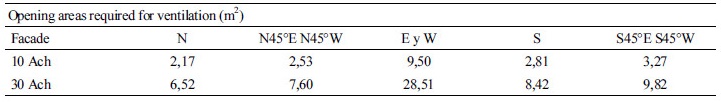
The open facade of the module has an area of 18 m2 which prevents the east (E) and west (W) facades from meeting optimal air exchanges. For this reason, the minimum air exchanges (10 Ach) as the comparison parameter. As it can be observed, façade (N) presents the lowest requirement of opening with 2.17 m2 while facades (E) and (W) present the highest value with 9.50 m2.
Natural Lighting
Simulations were performed according to the parameters outlined in the research base line, considering the following materials for each system: walls = semi-gloss white paint; floors = semi-gloss white finish; blinds = wood; profiles = aluminum and glass = clear glass.
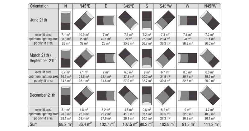
In Figure three (3) different values are identified at the work plane height (0.75 m from the floor surface), the areas of it that over lit, those that are properly illuminated and those that are poorly lit. As in figure 3, columns show the orientation of the open façade and the rows show the dates that were evaluated. At the end of the table the sum of the optimal lit areas was performed to identify the areas which have lighting independence throughout the year.
The orientations with the highest and lowest area in the final count, as shown in Figure 4 are the N45°W and N45°E facades, respectively.
Construction of the Tool
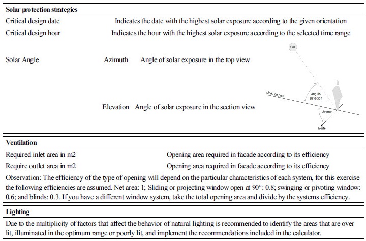
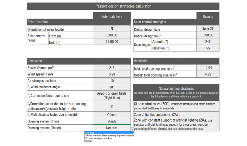
The proposed tool, was developed by building a calculator that allows to obtain basic outputs to generate solar control strategies, to identify areas of ventilation and promote the balance of the light curve according to the space needs. To use the calculator, the designer should enter the data requested in the first column. Each item of the column has a drop-down list where he/she must choose an option according to the project that will be developed; once the data is entered, the second column will display the design criteria, as shown in figure 5.
Table 2, shows the instructions on how to read the results obtained in the calculator.
Application Example. Case Study Medellin
This chapter contains an application example of the use of the passive design strategies calculator, which contains the development of the open façade of the hypothetical model proposed in the research base line. Passive design strategies are chosen for two (2) façade’s orientation, the (N) and the (W), which represented the most favorable and critical conditions, respectively, during the diagnosis of solar and wind exposure. As light's behavior is highly influence by the facades definition and other inner spaces characteristics, and not only by weather conditions, the other two environmental phenomena were taken as references for the selection of the best and worst initial design conditions.
As architectural approach, a flexible, modulated facade was chosen, dividing it into a basic grid with divisions of 1m in the horizontal and 0.6m in the vertical 0.6m. Each module is a projecting element which, when opened, casts shadow on the façade. This element is made of wooden slats framed in metal profiles, and inside, a clear glass that has no solar protection coefficient. The opening angle, density and size of the slats depend on the requirements for solar control of the façade’s orientation; the windows operation will be defined according to the ventilation needs. Inside the space, 0.75 m from the floor surface (work plane height) is taken as the evaluation height, and the dimensions of the Latin-American population are taken as a reference for comfort analysis purposes (Ávila, Prado, & González, 2007). The work station closest is located 1 m away from the façade, and a 1.2m high window seat is specified, which will not require solar protection.
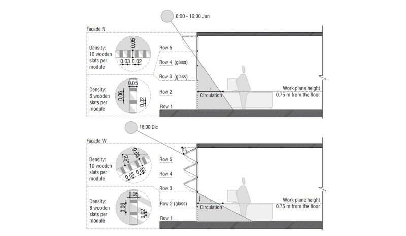
Solar Protection Criteria
For the distribution of the elements, facades were divided into rows. According to the defined range of solar control, Figure presents the design strategies apply for both facades, where rows that require solar protection are identified, and for those rows where protection is not needed, the dimensions of the wooden slats and densities of them are given for each panel.
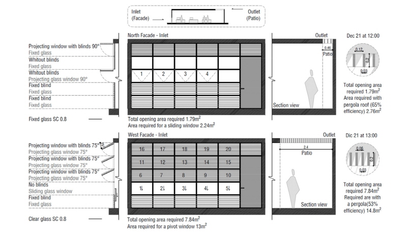
Natural Ventilation Criteria
The method used to calculate the areas required for ventilation, assumes two openings of equal size, one as an inlet and the other as an outlet. Table 2 gives the total opening area required, which is modified by the loss of efficiency, depending on the chosen opening system. The façade is assumed to be the inlet location, and a patio is located on the back of the module as the outlet. The space under the patio is not considered as an “useful area” and can receive sun and rain. Figure 7 shows the application of this elements in the hypothetical model.
Daylight Criteria
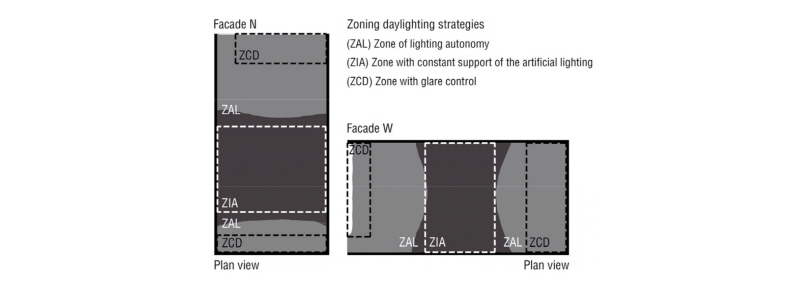
The lighting simulations were performed considering the new composition of the façade, which resulted from the applied solar control and natural ventilation criteria, and the location of the back patios. For each sample orientation the work plane areas which were over lit, illuminated in the optimum range of lightning levels or poorly lit, were identified. Based on this information, a space zoning was outlined in order to achieve a balance in the light curve, generating visual comfort for the space users and reducing energy consumption by preventing the unnecessary use of artificial lighting.
Each space is classified into three zones: areas of lighting autonomy (ZAL), areas with constant support of artificial lighting (ZIA) and glare control areas (ZCD). The first category includes all areas that present appropriate lightning levels within the optimal range required by the spatial typology; the second one gathers the areas of the work plane that are poorly lit and do not reach the minimum required lighting levels at any time of the year; finally, the third category refers to those areas that exceed the maximum levels, and therefore require glare control strategies, achievable by a proper definition of its materials and the operation of the inhabited space.
Conclusions
As it can be seen in the application example, for the architectural typology analyzed in this exercise, all orientations can get the same level of solar control, although the E and W facades require greater design efforts to obtain the same results in the indoor environment, than those required by facade N. However, it is important to consider that this refers only to solar shading, in future applications the influence of other variables, such as the thermal behavior, materials and different envelope compositions, should be evaluated.
In the model and the studied space type, it is not possible to achieve optimal Ach (30), when the space’s main open facade is parallel to the wind direction.
According the lighting diagnosis which was performed, between 40% and 50% of the total area of the work plane, have lighting autonomy, in both resulting inner environments. This value represents a significant portion of the area, which with a proper distribution of the electrical circuits, can be translated into energy savings by having a lower consumption due to artificial lighting use.
Having a tool that allows architects, unfamiliar with the subject of bioclimatic and solar passive design, to obtain basic guidelines to integrate the principles of this discipline to their designs, allows to project an architecture with a greater environmental quality for space users, which in return, decreases environmental impacts. This tool can be applied in the city of Medellin, and this methodology can be replicated in cities located in the tropics, which have similar climatic conditions.
