

Introduction
Experimental procedure
Materials preparation
Electrochemical measurements of the heat-treated plain carbon steels
Examination of the corroded specimen after dynamic polarization
Results and discussion
Microstructural observation of the plain carbon steels
Polarization curves
Corrosion mechanisms
Conclusions
Introduction
Steel is one of the most versatile engineering materials and has a wide range of applications across different sectors such as transport, structural, chemical, oil and gas, railways. The steel used in the present study contains different carbon (0.002%C, 0.17%C, 0.43%C, and 0.7%C) consisting of ferrite, ferrite-pearlite, and fully pearlite microstructures which have a wide range of applications [1, 2]. For instance, ultra-low carbon steels (0.002%C having ~ 100% ferrite) are widely used in automobile sectors due to their excellent formability and the ferrite-pearlite steels with 0.17% C and 0.43% C (having ~ 32.74 and ~ 52.34% pearlite phase, respectively) steels are frequently used as a beam in bridges, buildings, ships, and reinforcing bars. However, high carbon (~0.7%C) fully pearlite steel is broadly used in making high strength steel rope and rail [1]. Hence, steels are exposed to different classes of environments and get corrodes during application. Since the mechanical and electrochemical properties of plain carbon steels are directly interconnected to the composition and microstructures, hence, the composition and microstructures of the steels are the most critical parameters that guided the corrosion behaviour of steels [3, 4].
Steels mainly consist of two different phases ferrite, and cementite. Therefore, the compositional and structural difference between the ferrite, and cementite phases causes the difference in electrode potentials in an aqueous corrosive environment that leads to the formation of different types of micro galvanic couples which causes galvanic cell corrosion in steels. More active phase like ferrite (α-Fe) act as an anode and passive phase like cementite (Fe3C) acts as a cathode [5, 6]. Hence, throughout the corrosion of plain carbon steels, anodic dissolution of the soft ferrite phase occurs and leaves behind a skeleton of the undissolved hard cementite phase (Fe3C). Therefore, in micro-galvanic cell corrosion, the dissolution of the anodic ferrite phase is directly influenced by the interfacial area of cathodic phases (cementite) [6]. Hence, in micro-galvanic corrosion, as the cathodic (cementite) surface area is available for the cathodic reaction (O2+2H2O+4e- = 4OH-) increases more dissolution of the ferrite phase (Fe = Fe+2 + 2e-) take place [7, 8, 9]. Therefore, the microstructural and compositional influence on the corrosion behaviour is mainly due to the formation of the micro galvanic couples between the ferrite and cementite phases [10, 11, 12, 13].
Yumoto et al. [14] have successfully synthesized the cementite (Fe3C) films by the physical vapour deposition (PVD) method and noticed that the dissolution rate of the Fe3C was half of the Fe in 1% NaCl solution. Researchers have also found that the hydrogen overvoltage of Fe3C is relatively low as compared to the ferrite, and thus the cathodic reaction that occurs on the Fe3C phase speeds up the anodic dissolution reaction of the ferrite phase [15, 16, 17]. Similarly, Hao et al. [18] have also discovered that the ferrite phase dissolves more quickly than Fe3C, and the dissolution rate of ferrite increases with the increase of the amount of Fe3C in chloride solutions. They have reported that the increase of cementite-to-ferrite area ratio significantly increases the tendency of micro galvanic corrosion. Despite the lower dissolution rate of Fe3C as compared to ferrite, Fe3C appears in the form of the skeleton (act as the cathodic site), and hence, the anodic dissolution rate of ferrite further accelerates [14, 18].
Pearlitic steel is an alternate mixture of ferrite and cementite lamellae wherein hard cementite lamellae are embedded in a soft ferrite matrix. Therefore, the mechanical and electrochemical properties of the pearlite steel mainly depend upon the fraction of the pearlite, pearlite colonies size, and interlamellar spacings. The size, shape, and distribution of the galvanic couples can be different in different carbon steels (like ~100% ferrite, ferrite-pearlite steel with ~ 32.74 and ~ 52.34% pearlite, and ~100% pearlite), which depends on the fraction of pearlite, pearlite colony size, and interlamellar spacing that alter the corrosion susceptibility of the steel [6, 19, 20]. Many studies have been published on the corrosion behaviour of steels with different compositions and microstructures [21, 22]. For instance, Clover et al. [23] have reported that the various morphology of cementite and its distribution in ferrite matrix (parallel plates in pearlite and evenly distributed in tempered martensite) vary the interfacial area of the galvanic couples and, hence corrosion behaviour of steels influenced [23]. In one study, Katiyar et al. [2] have also reported that the finesses of the pearlite microstructures improved the corrosion resistance of rail steels. However, in another study, they have found that the corrosion rate increases as the carbon content increases since the area available for cathodic reaction increases [1].
Based on the previous studies it can be stated that the corrosion resistance of steel can be increased by improving the homogeneity of the phases and fineness of the microstructures [24, 25]. Literature has also suggested that the additional phase in the steel matrix adversely influenced the corrosion resistance of the steel due to the difference in the crystalline lattice structure as well as compositional variation in the phases that produce variations in the electrode potential [1, 2, 3, 4, 26, 30]. Hence, electrode potential difference among these dissimilar phases offers an additional driving force for the corrosion by dissolving the irons (Fe) atoms on the steel surface [26]. According to the results of previous works [1, 2, 3, 4, 27, 28, 29, 30], the corrosion resistance of pure iron and interstitial free (ultra-low carbon) steel has been claimed very high because of the presence of the insignificant carbide. However, in the case of medium and high carbon steels, the relative corrosion resistance has been reported to be low because the corrosion rate increases due to an increase in the cementite-to-ferrite area ratio [1, 2, 3].
Apart from % carbon content, the corrosion performance of the plain carbon steel also depends upon the Si and Mn content. However, the Si and Mn strongly affect the mechanical properties as compared to the corrosion properties. The corrosion behaviour of the plain carbon steel is mainly influenced by the presence the Si and Mn when they present in a larger amount. Therefore, the effect produced by Si and Mn is relatively low and very complex. In addition, its synergistic effect with carbon and different microstructures are difficult to determine, however, an increase in carbon leads to the formation of cementite that increases the corrosion rate. Hence, the variation in microstructures (such as the presence of %ferrite, fraction of pearlite, pearlite colony size, and interlamellar spacing) of steel is a more worthy approach to increase the corrosion performance of the plain carbon steels. After the extensive literature survey, it can be concluded that the corrosion behaviour of plain carbon steels and their corrosion-related problem is primarily associated with the steel microstructures, composition and the environments where these steels are exposed during their application [8, 19, 31]. However, detailed analysis of the role of interlamellar spacing on corrosion mechanisms of the low, medium, and high carbon (0.002%C, 0.17%C, 0.43%C, and 0.7%C) steels and the effect of four different variants of pearlite steels under different heat treatment conditions in freely aerated 3.5% NaCl solution are still far from understood. In addition, the scarcities in the literature of a wide range of composition and microstructure of pearlite and published contradictory results have implied that the corrosion behaviour study of these steels having a different fraction of pearlite microstructure is still a primary interest of the scientific community [1, 2].
There have been numerous studies on the corrosion behaviour of plain carbon steels. However, the detailed comparison in corrosion behaviour and their involved corrosion mechanisms of a low, medium, and high carbon steel with a wide range of ferrite (contains ~100% ferrite), ferrite-pearlite (having 0.17% C and 0.43% C consist of ~32.74 and ~52.34% pearlite, respectively), fully pearlite microstructures are still far from fully understood. Furthermore, the effect of pearlite morphology within the pearlite colony might also be an exciting addition to the current research in corrosion behavior of steels to appreciate the relative influence of carbon content and its associated different microstructures on the dissolution behaviour and corrosion mechanism. However, Katiyar et al. [1, 2] have published the individual results related to corrosion behaviour of four different variants of pearlite steel as well as four different carbon compositions of annealed steel. These results are mainly limited to understand the corrosion behaviour of either pearlite steel or different carbon steel which have their different objectives. However, the present work has another objective following interesting outcomes that have been obtained in our previous works [1, 2].
The present work discusses the effect of the role of interlamellar spacing and pearlite colony size on corrosion behaviour of plain carbon steels (0.002%C, 0.17%C, 0.43%C, and 0.7%C) under different heat treatment conditions. For this intention, ultra-low carbon (~100% ferrite), low and medium carbon (ferrite-pearlite steels having ~ 32.74% and ~ 52.34% pearlite phase, respectively) and high carbon steels (~100% pearlite) have been used in annealed conditions to examine the effect of pearlite on the corrosion behaviour of plain carbon steels. On the other hand, four different variants (coarse, medium, fine, and very fine) of pearlite steels have also been developed by suitable heat treatment process using the 0.7% carbon steels to understand the role of interlamellar spacings on corrosion mechanisms of the pearlite steels. The corrosion rate of all the steel was investigated through a dynamic polarization test in a freely aerated 3.5% NaCl solution. However, the corrosion mechanisms of the different microstructure (ferrite, ferrite/pearlite, and pearlite) steel were also studied in detail after dynamic polarization tests with the aid of micrographs of FE-SEM.
Experimental procedure
Materials preparation
Heat treatments of the plain carbon steels
The ultra-low, low, medium, and high carbon (0.002%C, 0.17%C, 0.43%C, and 0.7%C) steels and four different variants of (consisting of very coarse, medium, fine, and very fine) pearlite steels are selected for the present study to understand the corrosion behaviour and corrosion mechanisms of the steels. The detailed chemical composition of all the steels used in the experiments is given in Table 1. The ultra-low carbon steel was used as an as-received condition. The plain carbon steels specimens of dimensions 15 mm×15 mm×5 mm were cut. Then all the specimens were austenitized at the temperature of 950°C in a muffle furnace for a soaking time of 12 min. Subsequently, specimens were cooled by furnace cooling to get the annealed microstructure. However, four different coarse, medium, fine, and very fine pearlite steel of 0.7%C steel was obtained by furnace cooling, as-received condition, air-cooling (normalizing), and force air-cooling (force normalizing done by using the table fan) after austenitized at the temperature of 950°C in a muffle furnace for a soaking period of 12 min.
Table 1.
Compositions of the steels specimens used in the experiments (wt.%)
Microstructure of the heat-treated steel specimens
To obtain the micrographs of the plain carbon steels after heat treatment, steel specimens were polished mechanically by using the emery papers (silicon carbide) up to 2500 grit size. Finally, mirror polishing was done by using the alumina suspension of 0.05 micron-sized. Subsequently, all the specimens were etched (using the 3% Nital etchant) after cloth polishing to obtain the micrographs with the aid of scanning electron microscopy (Nova Nano FE-SEM 450).
Electrochemical measurements of the heat-treated plain carbon steels
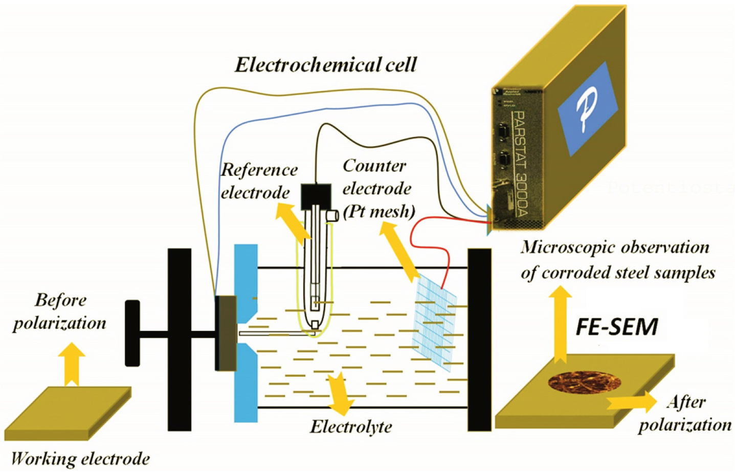
The objective of the present study was to comprehend the corrosion mechanisms of the plain carbon steels containing different compositions and microstructures with the aid of polarization tests. However, various details of the electrochemical results have been published elsewhere [1, 2]. Figure 1 depicts schematically the corrosion cell set-up. The corrosion tests were conducted in a flat bottom electrochemical cell with the aid of Parstat 2263 potentiostat (Princeton Applied Research, USA). The reference electrode used was a saturated calomel electrode (SCE). This has a +0.242 V of constant potential in reference to the standard hydrogen electrode at ambient temperature. However, the mesh of platinum metal was used as a counter electrode. The working electrodes were the heat-treated different microstructures steels. Before the dynamic polarization tests, steel specimens were polished up to 2500 grit size (using the by silicon carbide papers) and followed by mirror polishing with alumina (0.05 μm) suspension.
To ensure reproducibility, the dynamic polarization tests were conducted three times with identical conditions. The scan rate of 0.166 mV/s and the scan range of ±250 mVSCE (ASTM G102) were used in all the tests [32]. The polarized curves were used to estimate the corrosion current densities (icorr) of all the steel specimens. The corrosion rates of the specimens were then estimated by using the formula [32]:
where icorr was the corrosion current density, in µA/cm2, EW was the equivalent weight of Fe considering the oxidation number 2, and ρ was the density of the specimen (7.86 g/cm3).
Examination of the corroded specimen after dynamic polarization
The morphology of the corroded specimens just after polarization was examined with the aid of FE-SEM. The examination was immediately done after polarization tests to avoid the formation of rust on the specimen after corrosion. However, just after the polarization tests, no corrosion products were seen on the corroded specimens. The corroded specimens were examined after cleaning the salt using the running distilled water. That has helped to examine the corrosion mechanisms more precisely. However, after 24 h some corrosion products were also observed on the corroded surface.
Results and discussion
Microstructural observation of the plain carbon steels
The ultra-low carbon steel demonstrates a ferritic (~100% α-Fe) microstructure (Figure 2(a)) with very few amounts of tiny alloy carbides dispersed in the ferrite matrix since the carbon content is extremely low. The microstructures of low and medium carbon steels with typical ferrite-pearlite morphology are shown in Figures 2(b) and 2(c), respectively. The fraction of pearlite varied according to the carbon content (as shown in Table 2) and has calculated with the aid of ImageJ software. Figure 2(d) shows the microstructure of annealed specimen of coarse pearlite steel (0.7% C) consisting of ~100% pearlite. The average interlamellar spacing of the low, medium, and high carbon steels are measured to be 731.3±74.7 nm, 373.3±61.42 and 283.48±61.17 nm, respectively. However, the cementite-to-ferrite area ratio in the pearlite regions is measured to be 0.336, 0.514, and 0.601 for the low, medium-high carbon steels, respectively. The average thickness of the cementite and ferrite lamellae, interlamellar spacing, and colony size of the pearlite are also calculated with the aid of ImageJ software and shown in Table 2. The average interlamellar spacing of the coarse, medium-fine, and very fine pearlite steels are measured to be 283.48±61.17 nm, 254.75±54.92 nm, 236.39±33.43 nm, and 178.66±25.84 nm, respectively. The entangled cementite is formed in the forced air-cooled steel due to sluggish diffusion since the cooling rate is very high in the case of force air cooled steel.
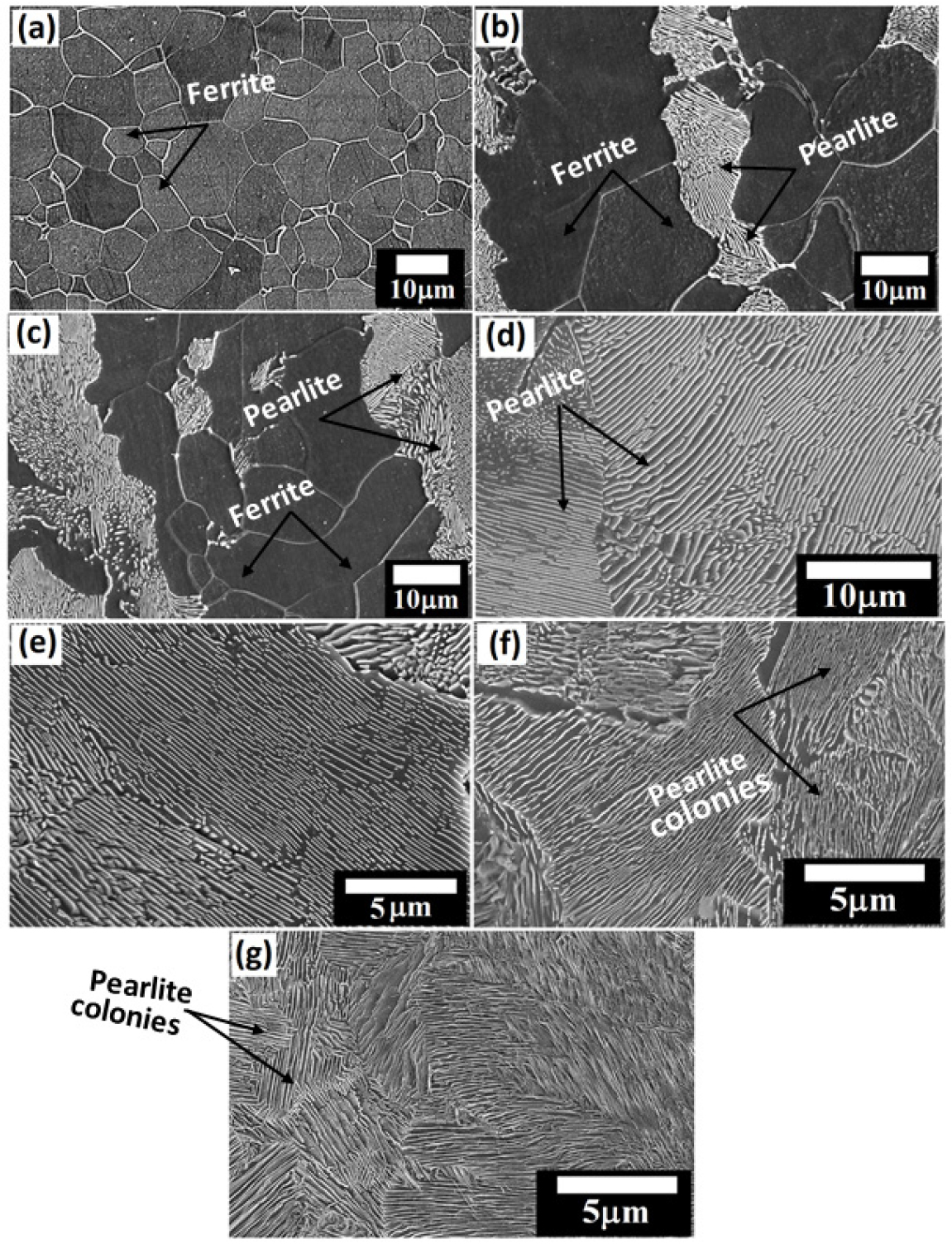
Figure 2.
FE-SEM images steel specimens: (a) ultra-low carbon (0.002%C) (~100% ferrite) (b) furnace cooled low carbon (0.17%C) and (c) medium carbon (0.43%C) ferrite-pearlite steels (d) furnace cooled (coarse) high carbon (0.7%C) pearlite steel (e) as-received (medium) pearlite steels (f) air-cooled (fine) pearlite steels, and (g) force air-cooled (very-fine) pearlite steels.
Table 2.
Different microstructural properties of low, medium and high carbon (0.002%C, 0.17%C, 0.43%C, and 0.7%C) under different heat-treatment conditions [1, 2]
Polarization curves
Figure 3 depicts the potentiodynamic curves for the ultra-low, low, medium, and high carbon steels (Figure 3(a)) and four different variants (coarse, medium, fine, and very fine pearlite) of pearlite steels (Figure 3(b)) in a freely aerated 3.5% NaCl solution. The various polarization parameters, corrosion potential (Ecorr), corrosion current density (icorr), and corrosion rate (mm/y), are presented in Table 3. Figure 3 shows that the cathodic part of the polarization curves is very much diffusion-controlled this signifies that the corrosion rate is mainly limited by the oxygen cathodic current density for all the steels. Therefore, the cathodic reaction (O2 + H2O + 4e = 4OH-) and anodic reaction (Fe = Fe+2 + 2e-) are occurred preferentially at the cementite and ferrite phases, respectively since ferrite is more anodic as compared to cementite (Fe3C). The corrosion rate of the different carbon (0.002% C, 0.17% C, 0.43% C, and 0.7% C) steels increases with the carbon content (as shown in Table 3). The ultra-low carbon steel has shown the lowest corrosion rate among all the (low, medium, and high carbon) steels (Figure 3(a)) since the cementite phase is not present. An interesting phenomenon is observed for 0.17% C to 0.43% C, and 0.7% C steels since an increase in the corrosion rate have been sluggish with the increase of carbon content.
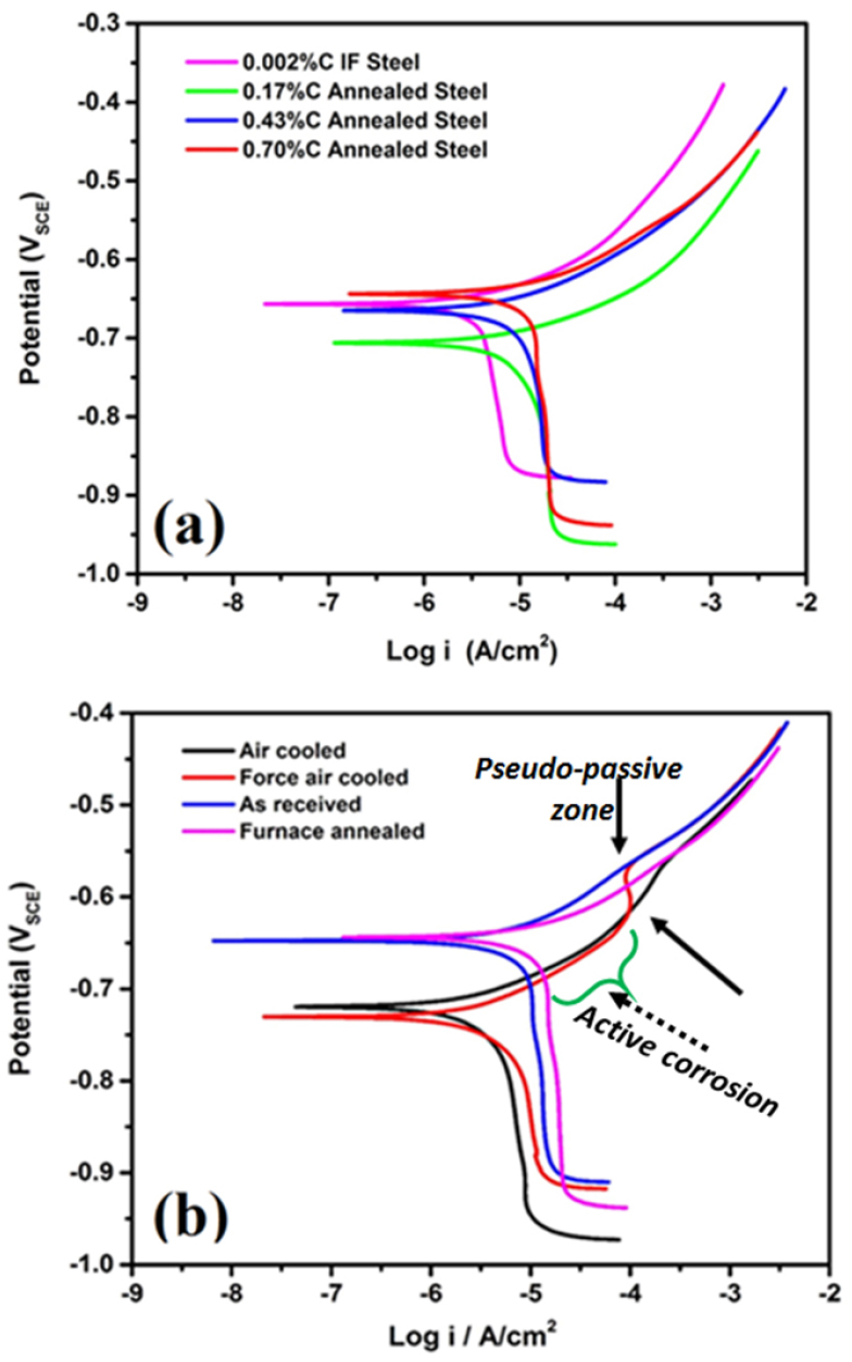
Figure 3.
Polarization plots of the (a) 0.002% C, 0.17% C, 0.43% C, and 0.7% C steel specimens and (b) four different variants of (consisting of very coarse, medium, fine and very fine) pearlite steels in freely aerated 3.5% NaCl solution at a scan rate of 0.166 mV/s (pair of arrowhead indicates the pseudo-passivity in the case of force air-cooled polarization curve and dotted arrow indicates the active corrosion) [1, 2].
Table 3.
In contrast, the corrosion potential (Ecorr) of the ultra-low carbon steel (as shown in Table 3) almost shows identical behaviour as reported in the literature [2, 8, 31]. The Ecorr value of the low carbon (0.17% C) steel decreases due to the presence of the pearlite (~32.74%) since no pearlite has been observed in the case of 0.002% C steel. After that, the Ecorr value has increased with the increase of carbon (0.43% C and 0.7% C steels) as well as pearlite content (~52.34% and ~100%, respectively). In the same way, Osório et al. [33] have also witnessed the identical behaviour and significant displacement of corrosion potential for the ultra-low carbon steel (- 629 mV) to low carbon steel (-705 mV). This has been attributed to the absence of pearlite (%) in the ultra-low carbon steels. The corrosion rate increases as the carbon content increase since the fraction of pearlite increases. Researchers have also reported that the cementite and ferrite lamellae form the galvanic couples due to the different electrode potential in between them in the pearlite regions that enhance the corrosion rates [1, 2]. Hence, as the fraction of pearlite increases corrosion rate also increases. Therefore, it can be concluded that the cathodic activity on the cementite phase enhances the oxygen reduction due to increases of % pearlite attributed to the higher corrosion rates in 0.17%C steel. Hence, the corrosion rate of the 0.43%C steel is high as compared to the low carbon steels since the fraction of pearlite increases which enhance the corrosion susceptibility in the ferrite regions.
One interesting fact has also been noticed in the low (0.17% C) and medium carbon (0.43% C) steels since the pearlite colony regions act as cathodes for the ferrite phase. Hence, as the cathodic area (fraction of pearlite) increases corrosion rate increases. However, up to this point, the effect of the interlamellar spacing and colony size of the pearlite on corrosion behaviour is unclear. To understand the role of interlamellar spacing on corrosion behaviour, four different variants of pearlite steel (consisting of very coarse, medium, fine, and very fine microstructures) have been intentionally prepared by the heat-treatment process. The corrosion rate of pearlite steel decreases in the following sequence coarse (furnace cooled)˗ medium (as received) ˗ very fine (force air-cooled) and˗ fine (air-cooled) (Figure 3(b)). The polarization tests have also confirmed that the corrosion susceptibility of the four different variants of pearlite steel depends upon the finesse (interlamellar spacing and colony size of the pearlite) of the microstructures. An interesting outcome confirms that the corrosion rate of air-cooled steel is very low as compared to force air cooled steel due to the entanglement of cementite lamellae in the case of force air-cooled steel. Interestingly, the pair of arrowheads indicate the pseudo-passivity in the case of force air-cooled steel, and the dotted arrow indicates the active corrosion (Figure 3(b)) which can be explained further with the help of FE-SEM micrographs.
However, the corrosion potential of coarse (-643.2 mVSCE), medium (-646.5 mVSCE), fine (-715.6 mVSCE), and very fine (-728.7 mVSCE) pearlite steel decreases as the interlamellar spacing decreases (Figure 3(b)). This signifies that the fine pearlite colonies and lower interlamellar spacing increase the corrosion tendency of the pearlite steel since the corrosion potential signifies the corrosion tendency but not corrosion rate and hence, the obtained corrosion rate trends have been found different. However, the corrosion current density is more important in determining the actual corrosion rate of a material which can be further explained by examining the surface of the corroded specimen using the FE-SEM micrographs. Since the corrosion current is a kinetic value (the corrosion rate is proportional to corrosion current density) and corrosion potential is thermodynamic value. The nobler the corrosion potential the lower would be the associated corrosion current density. Therefore the kinetics of the cathodic reactions, the area where cathodic reactions can occur, would decide the corrosion rate which increases as the carbon content increases [1, 2].
Corrosion mechanisms
To examine the dissolution mechanisms and corrosion performance of all the steel, the corroded specimens are subjected to microstructural observation after polarization tests without the aid of etching. This has enabled the understanding of the corrosion mechanism in steels after the polarization tests.
Figure 4 depict the microstructures of the ultra-low carbon steel (0.002%C) before and after the polarization tests. Figure 4(a) describes the microstructure of the ultra-low carbon steels which consists of grain boundaries. The average grain size of the ultra-low carbon steels is calculated to be 10.15±5 μm. There is no sign of cementite or pearlite since the ultra-low carbon steel contains very low carbon (0.002%C). This microstructure is obtained after etching the ultra-low carbon steels in a 3% Nital solution. Since this steel contains ultra-low carbon, there are very few tiny carbides has observed on the surface of the ferrite grains. This implies less corrosion attack on the ultra-low carbon steels hence lower corrosion rate is obtained after polarization tests. Figure 4(b) shows the corroded morphology of the ultra-low carbon steel after polarization tests. It confirms the uniform corrosion with the occurrence of dispersed localized attacks. Since the ultra-low carbon steel contains predominantly ferritic phase with the presence of local and extremely fine alloy carbides, the formation of local galvanic cells has occurred that initiating local corrosion susceptible region (as shown in Figure 4(c)) [34].
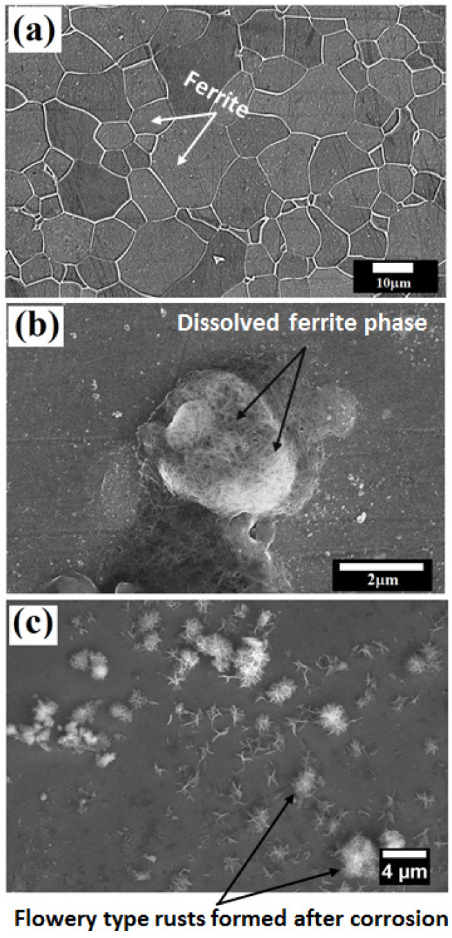
Figure 4.
(a) Microstructure of the ultra-low carbon steel obtained after Nital etching (b) micrographs obtained just after the potentiodynamic polarization tests shows the local attack on the ultra-low carbon steel surface (c) micrographs of the corroded specimen obtained after 24 h after the potentiodynamic polarization tests show the flowery types rust morphology.
The corrosion mechanism of ultra-low carbon steel (contains ~100% ferrite) is also depicted schematically in Figure 5. Since the grain boundaries region are more active (act as an anode) as compared to the grains (act as a cathode) significant microcell corrosion has occurred along the grain boundaries.
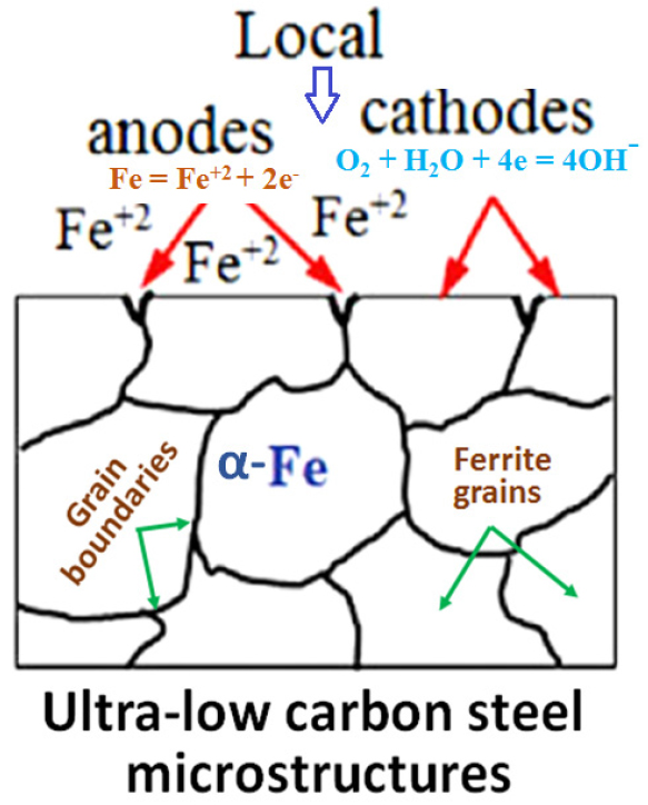
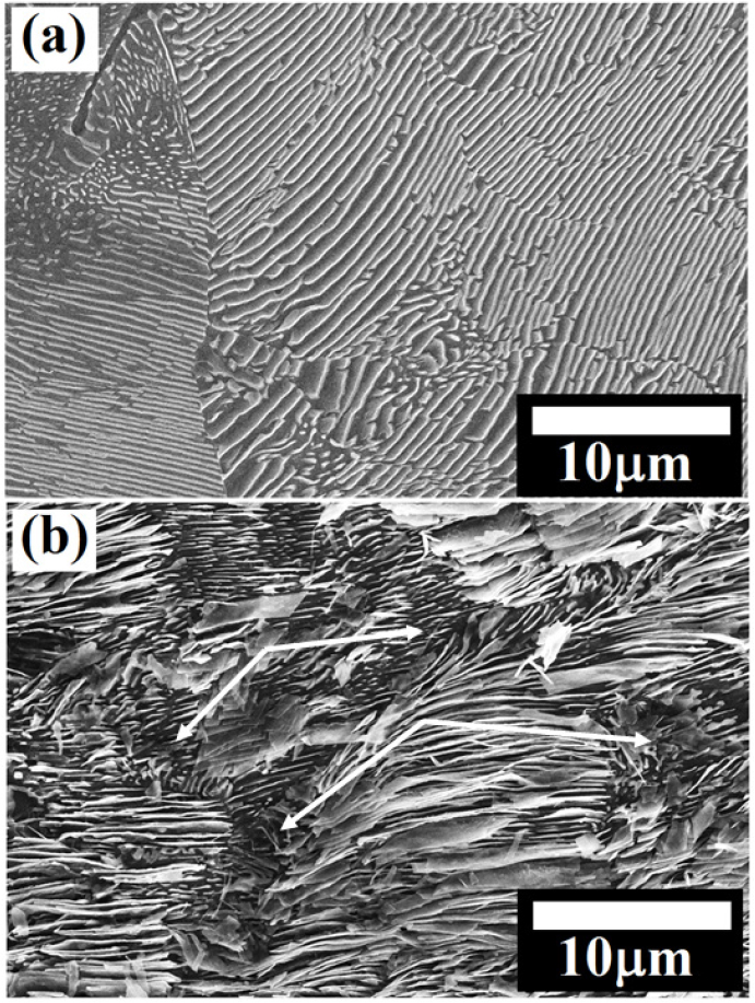
Figure 6(a) depicts the microstructure of the low carbon (0.17% C) steel obtained after cloth polishing followed by 3% Nital etching. The average colony size and the fraction of pearlite of the 0.17% C steel are calculated to be 26.62±4.94 μm and ~32.74%, respectively. Figure 6(b) shows the corroded morphology of 0.17% C steel after polarization tests. Significant dissolution is observed at the pro-eutectoid ferrite regions as compared to the pearlite regions since pro-eutectoid ferrite regions are chemically more active (act as an anode) as compared to the pearlite in a 3.5% NaCl solution. Intense dissolution has also been observed within the pearlite colonies since ferrite lamellae selectively dissolved and cementite lamellae remain undissolved. Hence, alternate galvanic couples have also formed within the pearlite colonies causing the micro-galvanic cell corrosion (as shown in Figure 6(c)). Figure 6(d) depicts the micrographs of the corroded specimen obtained after 24 h after the polarization test displays the pop out of the pearlite colonies adjacent to the corroded pro-eutectoid ferrite regions.
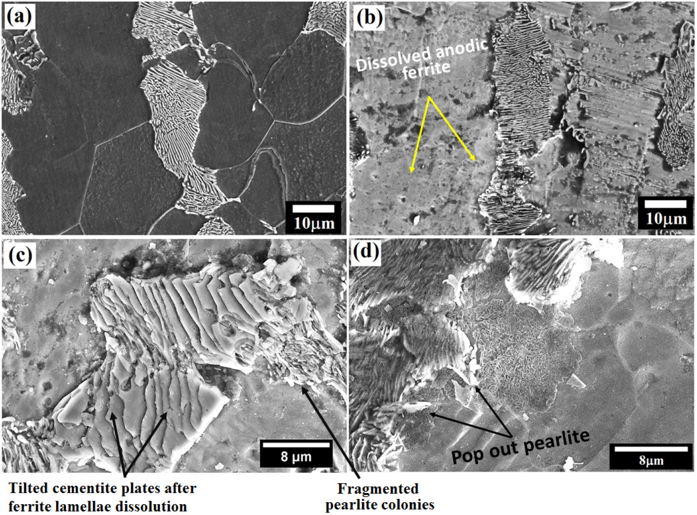
Figure 6.
(a) Microstructure of the low carbon (0.17% C) steel obtained after Nital etching (b and c) micrographs obtained just after the polarization tests. The intense dissolution at the pro-eutectoid ferrite regions and local attack on the ferrite lamellae in pearlite colonies is observed (d) micrographs of the corroded specimen obtained after 24 h after the polarization tests.
The schematic representation of the micro galvanic cell corrosion of 0.17%C steel is shown in Figure 7. The figure confirms that the ferritic lamellae and pro-eutectoid ferrite phases dissolved due to their anodic nature and the undissolved remaining cementite phase progressively accumulates on the steel surface and enhanced the cathodic surface area [35]. Hence, the dissolution of ferrite lamellae is more prominent since it is galvanic coupled with the cementite lamellae, which act as a cathodic component, where a cathodic reduction occurs (as shown in Figure 8(b)). Published results have also confirmed that the ferrite and cementite lamellae in pearlitic steels have corroded by forming galvanic cell corrosion [35]. Therefore, the increase and decrease of interlamellar spacing and fraction of pearlite have significantly influenced the corrosion performance of the steels.
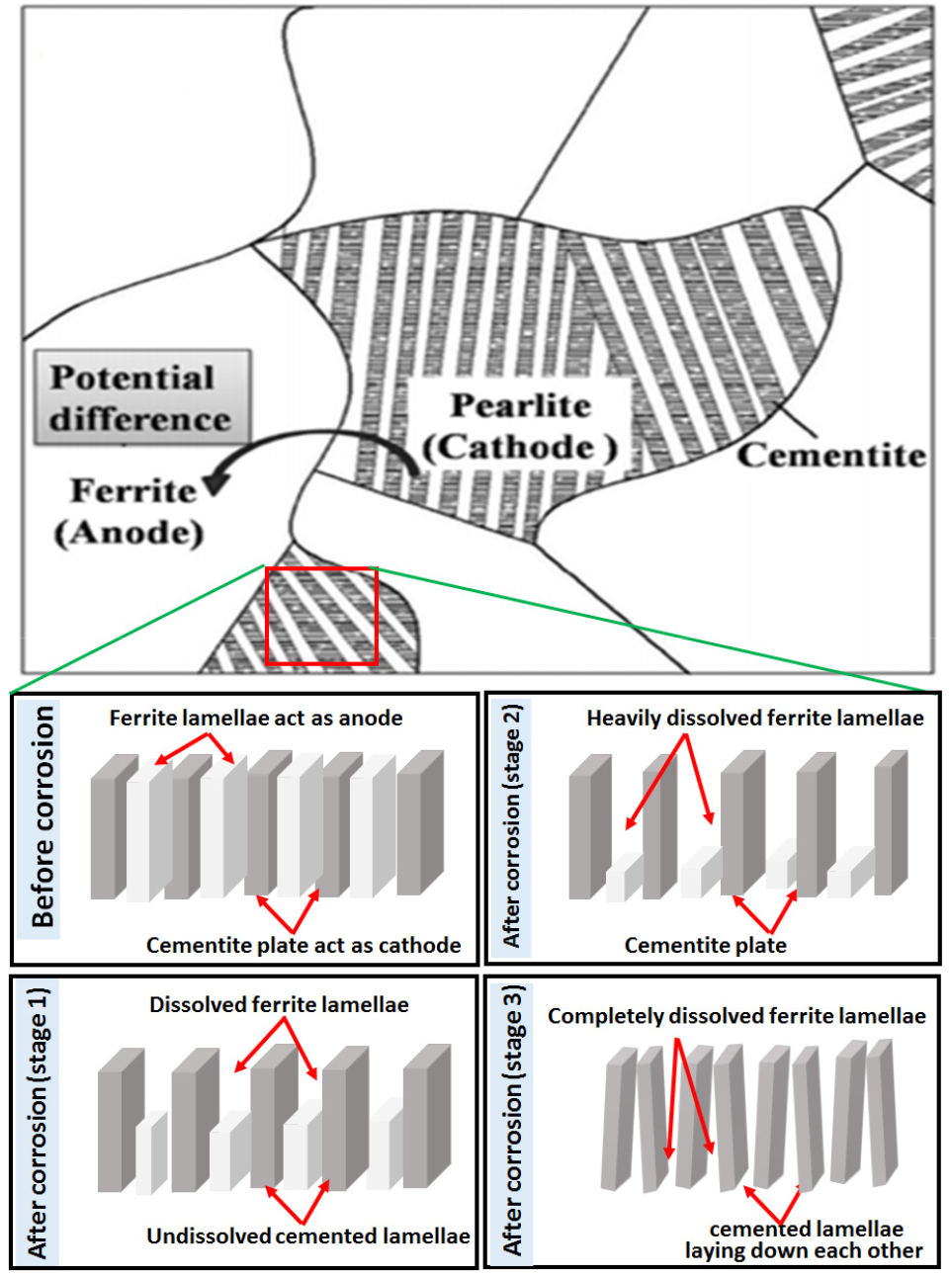
Figure 8 shows the typical corroded FE-SEM images of the 0.17%C steel obtained after polarization tests. Intense dissolution of pro-eutectoid ferrite phase has occurred adjacent to the pearlite colony signifies that the whole pearlite colony behave as a cathode which accelerates the dissolution of the ferrite phase and ultimately leads to the pop-out of the cementite (Figure 8(a)). In addition, differential dissolution characteristics of the pearlite colonies have indicated the dis-continuous network of alternate ferrite and cementite lamellae and uneven interlamellar spacing (Figure 8(b)).
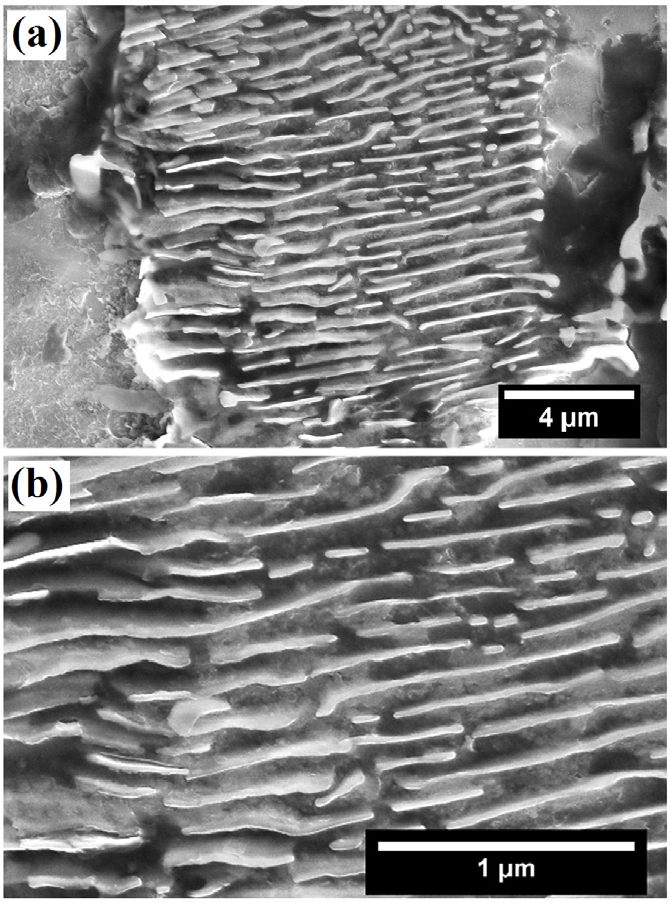
Figure 8.
FE-SEM images of the corroded 0.17%C steel (a) typical intense dissolution of pro-eutectoid ferrite region have observed adjacent to the pearlite colony (b) typical dissolution behaviour of pearlite colonies signifies the dissolved ferrite and undissolved cementite lamellae after polarization tests.
Figure 9(a) shows the FE-SEM images of the medium carbon (0.43% C) steels which contain ~52.34% pearlite with grains size of 18.38±4.12 µm. The comparable tendency in the dissolution pattern has also been seen in the case of the medium carbon (0.43% C) steel (Figures 9(b) and 9(c)). But, the only difference in the degree of attack are observed in the pro-eutectoid ferritic region as well as in the ferrite lamellae in the pearlite zone. Since the area fraction of the ferrite (anode area) is less (~47.66% in 0.43% C steel) as compared to the pearlite (cathode), popping out of the pearlite is more prominent (Figures. 9(b) and 9(c)). Less anodic regions have significantly enhanced the aggressiveness of the galvanic attack in micro galvanic corrosion. In addition, some fragmented cementite plates detached from the pearlite colony can also be seen in Figure 9(c). Heavily corroded morphology of the rusts can be seen after 24 h of the polarization test.
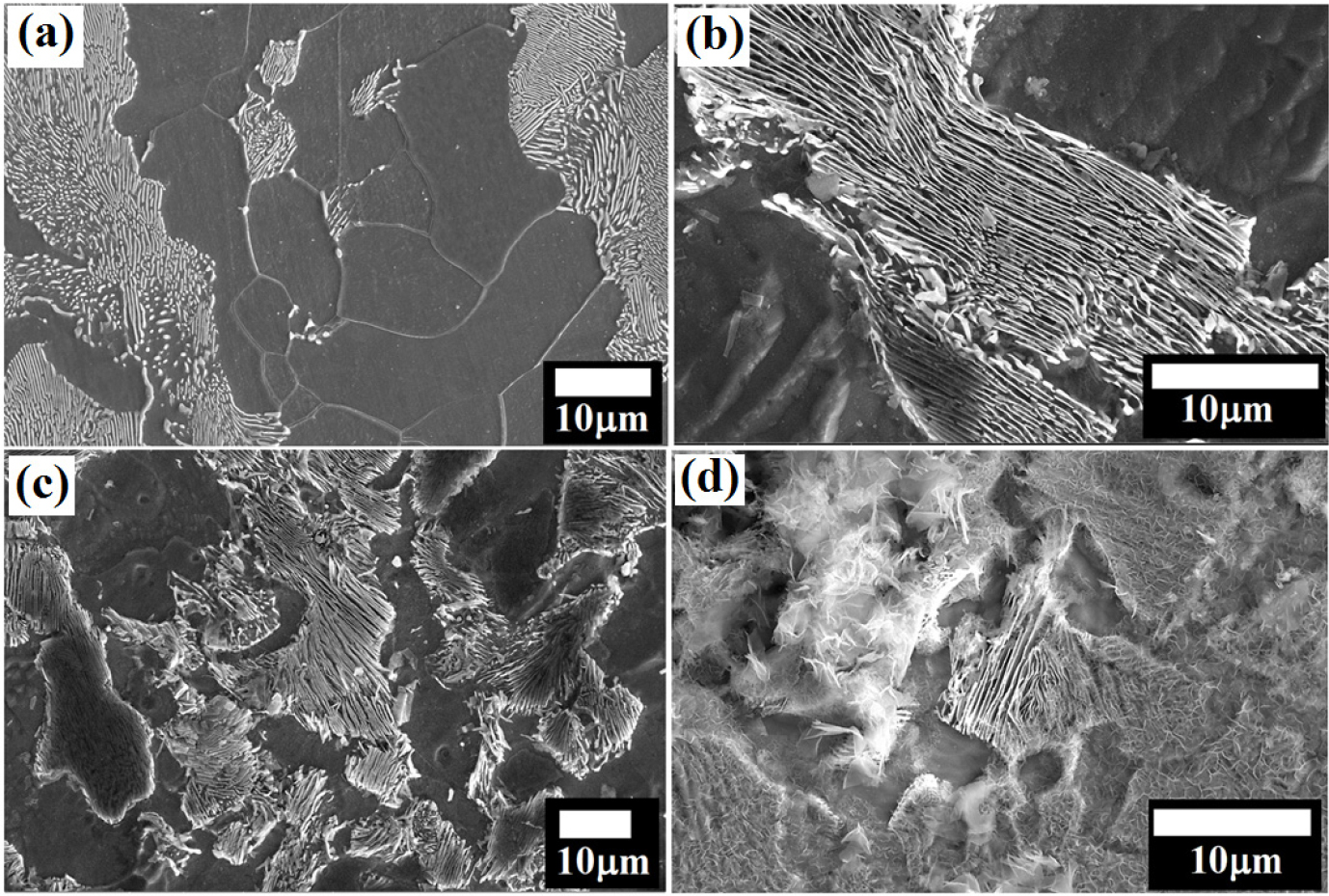
Figure 9.
(a) Microstructure of the medium carbon (0.43% C) steel (b) intense dissolution of pro-eutectoid ferrite region extruded the cementite from the pearlite after corrosion (c) typical corrosion attack on the ferrite-pearlite steel (d) heavily corroded ferrite-pearlite (0.43% C) steel after 24 h of the polarization test.
The corrosion behaviour of ferrite-pearlite microstructure can be easily understood with the help of schematic representation (as shown in Figure 10). Li et al. [35] observed the microcell corrosion in ferrite-pearlite (0.15% C) steel. It is generally expected that the presence of various constituent phases in chloride-containing environments acts as initiation sites for localized corrosion. Hence, the micro galvanic cell reaction causes the corrosion of medium carbon steel. Due to an anodic reaction, the dissolution of Fe takes place and formed the unstable rusts (Fe(OH)2), which is further oxidized and transformed into the stable Fe2O3 rust [24]. Li et al. [35] have also compared the corrosion performance of ferritic steels (having different orientations) with ferrite-pearlite steel. They reported a higher corrosion tendency of ferritic-pearlitic steel as compared to ultra-low carbon ferritic steel [35]. However, the potential difference between these neighbouring grains (due to different atomic packings) is very small, which leads to the weaker galvanic couples as compared to the ferrite-pearlite microstructure. Therefore, ultra-low carbon steel is less susceptible to corrosion.
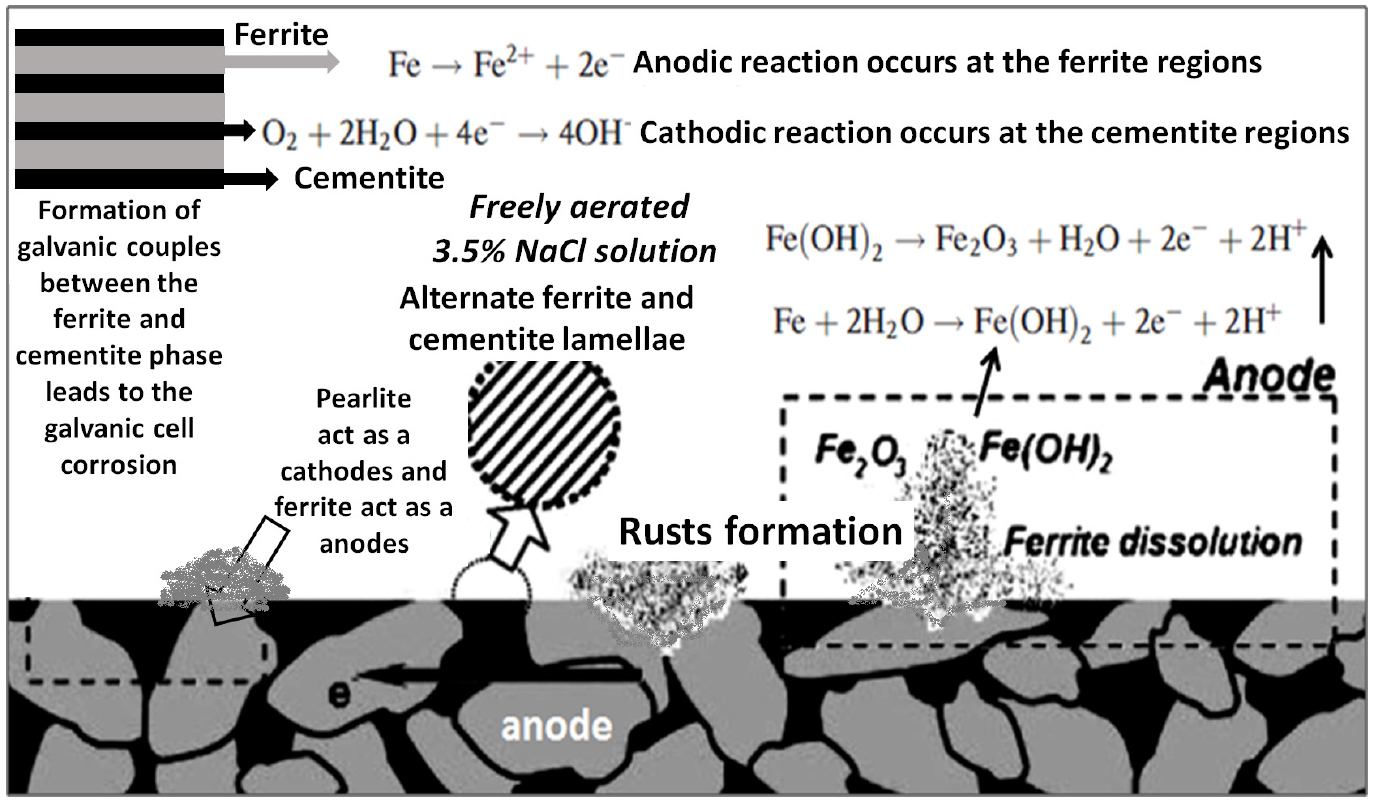
Figure 11 shows the microstructure of the annealed pearlite steel. The annealed pearlite steel consists of 34.34±9.90 µm average pearlite grain size having an average interlamellar spacing of 283.48±61.17 nm (as shown in Figure 11(a)). Figure 10(b) shows the corroded annealed pearlite specimens after the polarization tests. Intense dissolution can be seen along with the interface of the pearlitic colonies as well as within the pearlite that leads to the fragmentation of cementite.
As compared to the low and medium carbon steels, intense dissolution of the ferrite lamellae and the undissolved skeleton of the cementite plates are observed in the case of fully pearlite steel. Since the pearlite content is ~100% in 0.7%C annealed steel, the size of the cementite plates could impart a significant effect on the corrosion rate as compared to the ferrite-pearlite (low and medium carbon) steels. Besides, the interfacial area between cementite and ferrite lamellae is decided the overall corrosion rates. Hence, the maximum rate of corrosion is obtained in the case of annealed 0.7%C steel. Therefore, it can be specified that the higher cementite-to-ferrite area ratio and the presence of ~100% pearlite ascribed to the larger corrosion rate in the case of annealed 0.7%C steel.
Figure 12(a) depicts the FE-SEM images of the as-received (0.7%C) cold-rolled pearlite steel which is used for rail making. As-received pearlite steel consists of an average 28.02±6.80 µm pearlite colony size with an average 254.75±54.92 nm interlamellar spacing. However, dissolution behaviour and corrosion mechanisms of the as-received (0.7%C) pearlite steel is similar as observed in the case of annealed pearlite specimens (Figure 12(b)). Since as-received pearlite steel is the rolled product hence, more fragmented cementite lamellae have been observed (see in Figure 12(b)) after the dissolution of ferrite lamellae. However, the corrosion rate of these steels has further enhanced due to the increase of the interfacial area of the cementite phase after the dissolution of the ferrite lamellae phase since the undissolved remaining fragmented cementite plates progressively accumulate on the steel surface has enhanced the cathodic surface area (Figure 12(b)).
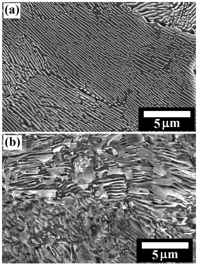
Figure 13(a) shows the microstructure of the air-cooled pearlite steel obtained after cloth polishing followed by 3% Nital etching. The pearlite colony size and interlamellar spacing of air-cooled pearlite steel are measured to be 25.82±5.75 µm and 236.39±33.43 nm, respectively, which are lower as compared to the annealed and as-received specimens. In the air-cooled steel specimens, corrosion is more pronounced along with the pearlite colonies interface (as shown in Figure 13(b)) however, less as compared to the as-received and annealed pearlite steel that is also confirmed in the form of fragmentation of the cementite lamellae from the pearlite (see in Figure 13(c)). Figure 13(c) is the magnified image of Figure 13(b).
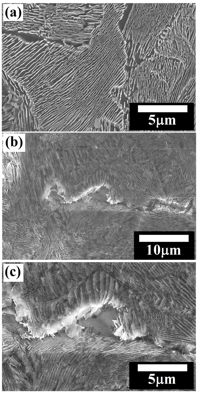
Figure 14 shows the schematic illustration of the comparative corrosion mechanisms and dissolution behaviour of the annealed, as-received, and air-cooled pearlite steel specimens. The basic corrosion mechanisms are the same for all the steels but the extent of the dissolution is varied as the interlamellar spacing of pearlite decreases. Therefore, the exposure of the aligned cementite plates surface on the corroded side surface is larger in the coarse pearlite steel. Once the surface is fully occupied with cementite plates, which is the manifestation of finer interlamellar spacing, further corrosion rate sluggish because of the fine capillary formed between the side by side aligned cementite plates after ferrite dissolution. However, the dissolution rate of ferrite lamellae would get sluggish and hence corrosion rate decreases. Subsequently, the mean depth of dissolution is higher in the case of annealed specimens followed by as-received and air-cooled specimens [36].
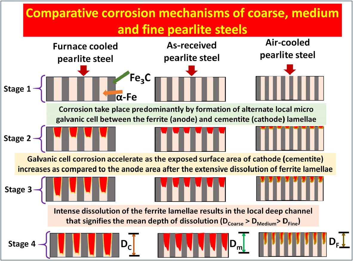
Figure 14.
Schematic illustration of the comparative corrosion mechanisms and dissolution behaviour of annealed, as-received, and air-cooled pearlite steel. The extent of corrosion is different however, the corrosion takes place progressively in the fashion of the formation of millions of alternate local micro galvanic cells between the ferrite (α-Fe) and cementite (Fe3C) lamellae. The mean depth of dissolution for annealed (coarse) as-received (medium) and air-cooled (fine) specimens are denoted by the DC, DM, and DF.
Figure 15(a) shows the FE-SEM micrograph of the force air-cooled steel specimens obtained after cloth polishing followed by 3% Nital etching. The force air-cooled steel specimens consist of an average pearlite colony size and interlamellar spacing are 20.85±3.99 µm and 178.66±25.84 nm, respectively. The basic corrosion mechanisms are similar as observed in the case of air-cooled steel (as shown in Figure 15(b)) except the entangled cementite largely alters the corrosion mechanisms in the force air-cooled steel. Therefore, the relatively significant corrosion along the pearlite colony interface can be judged in the form of broken cementite (fragmented cementite) which is normally observed after the intense dissolution of ferrite lamellae that leads to the separation and fragmentation of cementite lamellae plate from the ferrite matrix. Figure 15(c) has confirmed the different dissolution mechanisms since the fragmentation of entangled cementite lamellae leads to the larger dissolution after forming the galvanic couples since cementite lamellae have inter-connected to each other. However, the force air-cooled pearlite steel shows pseudo-passivity since the interlamellar spacing are very low (as shown in Figure 3(b)).
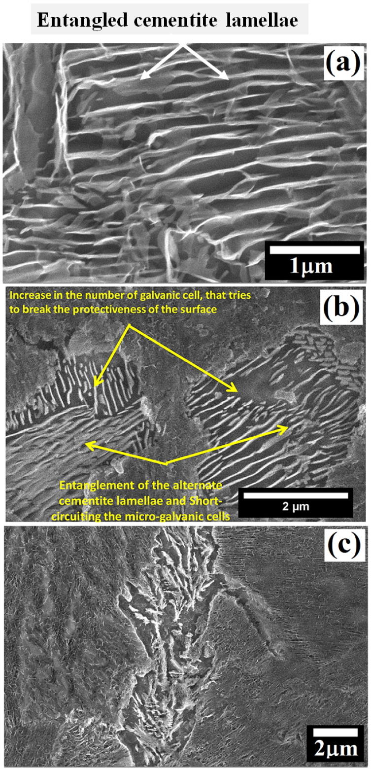
While comparing the corrosion behaviour of the air-cooled and forced air-cooled corroded specimens, intense dissolution, in some regions, is observed in the case of force air-cooled pearlite steel after showing the pseudo-passivity. Since the entangled cementite lamellae are more in the case of the forced air-cooled steel, causing to increase the short-circuiting of the micro-galvanic cells. Hence, the physical area of the galvanic cell also increases which further tries to break the protectiveness of the surface. Figure 16 schematically depicts the corrosion mechanism of the force air-cooled pearlite steel which help to understand the corrosion behaviour of this steel. Since the cementite lamellae have entangled (inter-connected to each other) in the case of the forced air-cooled specimen, the formation of the galvanic couples are different in shape and size as compared to the alternate lamellar structure of an air-cooled specimen.
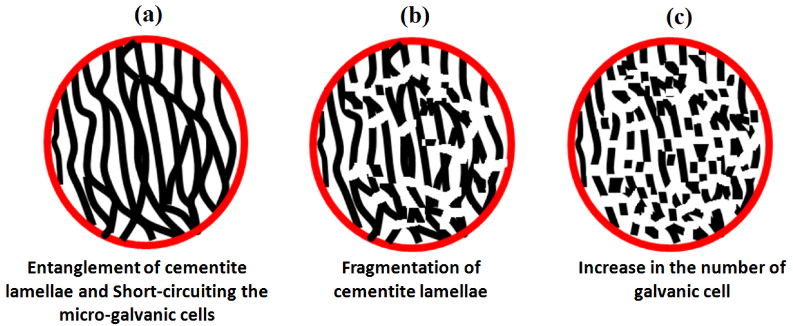
Figure 16.
Schematic representation of the (a) entanglement of the alternate cementite lamellae (b) each cementite lamellae connected to others has created short-circuiting of the micro-galvanic cells resulting in fragmentation of cementite lamellae (c) increase in the number of galvanic cells causing an increase in corrosion rate.
However, short-circuiting of the micro-galvanic cells (each fragmented cementite connected to another plate of cementite) has increased the number of galvanic couples that attempts to break the protectiveness of the surface in the case of the forced air-cooled specimen rather than air-cooled steel which mainly comprises of alternate galvanic couples. Hence, it can be expected that the entangled cementite lamellae could be broken and separated after the dissolution of ferrite in the form of small carbides which have a larger surface area as compared to the cementite lamellae. Therefore, a large number of micro-galvanic cells has formed and this would lead to an increase in the physical area of the galvanic cell corrosion. The corrosion behaviour of all the steel is obtained different because the rate of cathodic reaction is dependent upon the diffusion of oxygen from the bulk solution to the specimen electrode surface since the maximum solubility of oxygen in water is limited at room temperature and all the cathodic reaction occurs on the cementite. This could be attributed to the fact that the cathodic reduction rate was diffusion controlled. As a result, the rate of the cathodic reaction of plain carbon steels is diffusion-limited and hence, the overall corrosion rate is controlled through concentration polarization [7].
Figure 17(a) shows the correlation of the effect of carbon content, the fraction of pearlite, and interlamellar spacing on the average corrosion current density and corrosion potential value. An increase in carbon content from 0.002%C to 0.17%C leads to a substantial change in the corrosion behaviour since corrosion current density increases and Ecorr value is observed to be shifted in a more negative direction. This is because of the 0.002%C content only ferrite phase (~100% ferrite) however, 0.17%C steel content ~32.74% pearlite. Hence, in the presence of pearlite, the cathodic activity has increased significantly, resulting in higher corrosion current density and lower Ecorr values are obtained since pearlite colonies act as cathodes. As the carbon content increased from 0.17%C to 0.43%C to 0.70%C, the fraction of pearlite increased hence the corrosion current density has also increased since the galvanic cell reaction increases but the Ecorr value has shifted to the more noble direction. However, an increase in carbon (from 0.17%C to 0.43%C to 0.70%C) sluggish the corrosion susceptibility (as obtained from 0.002%C to 0.17%C) since the interlamellar spacing is decreased which has tried to suppress the corrosion tendency. Hence, the overall corrosion susceptibility is very high from 0.002%C to 0.17%C, and then sluggish from 0.17%C to 0.43%C to 0.70%C since the Ecorr value has shifted to the more noble direction (from 0.17%C to 0.43%C to 0.70%C) because of the size of the interlamellar spacing decreases. Therefore, we conclude that the lower interlamellar spacing of pearlite colonies helps to decrease the corrosion susceptibility of annealed plain carbon steels.
Figure 17(b) shows the correlation between the fineness of the pearlite on corrosion behaviour. The corrosion susceptibility of the pearlite steel very much depends upon the very fine average pearlite colony size and the lower interlamellar spacing since the fraction of pearlite is constant (~100%). As the average interlamellar spacing and average pearlite colony size decreases, the corrosion potential value has shifted to a more negative direction that signifies the higher corrosion tendency. However, the corrosion susceptibility of 0.7%C pearlite steel increase in the following sequence; air-cooled ˗ forced air-cooled ˗ as received ˗ furnace annealed steel since variations in the finesse of the pearlite microstructure significantly alter the corrosion behaviour of pearlite steels. The corrosion rate of air-cooled fine pearlite steel is lower than the force air-cooled very fine pearlite since the entanglement of cementite lamellae has altered the formation of galvanic couples after the corrosion. The cementite lamellae have broken after ferrite lamellae dissolution during the galvanic cell corrosion in freely aerated 3.5%NaCl solution. Hence, the corrosion performance of air-cooled steel is better than the force air-cooled steel.
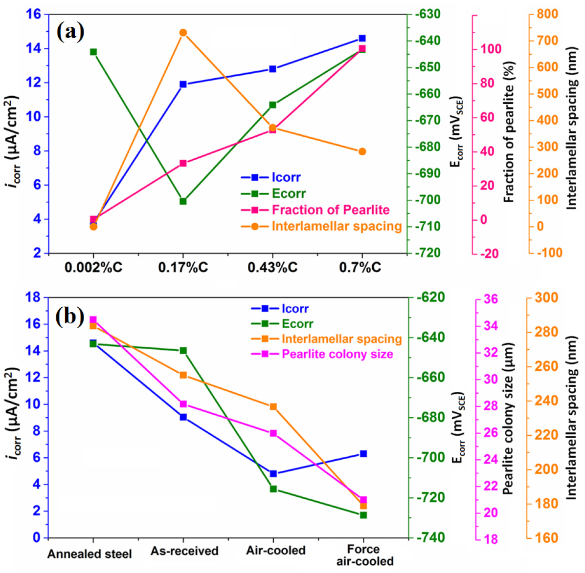
Figure 17.
(a) Correlation of the carbon content, fraction of pearlite, and interlamellar spacing on the average corrosion current density and corrosion potential value (b) the correlation between the fineness of the pearlite (coarse, medium, fine, and very fine) microstructures on corrosion current density and corrosion potential value.
Figure 18 shows the effect of carbon content, fraction of pearlite, pearlite colony size, and interlamellar spacing on the average corrosion current density and corrosion potential value. Initially, the corrosion rate has increased because the fraction of pearlite increased (from ultra-low carbon steel (0.002%C)-coarse pearlite (0.7%C)) since the pearlite colony act as a cathode and the increase in cathode surface area causes the higher galvanic cell corrosion. Once the fraction of pearlite has attained its maximum value (~100%), the corrosion susceptibility of the steel has further controlled by the finesse of the (interlamellar spacing) of the pearlite steels. Hence, air-cooled and force air-cooled pearlite steels have shown a lower corrosion rate as compared to the 0.17%C and 0.43%C steels since the interlamellar spacing in pearlite regions is higher in the case of 0.17%C and 0.43%C steels. Therefore, interlamellar spacing of the pearlite regions has played a critical role to control the corrosion behaviour of plain carbon steels. On the other hand, the pearlite colony size and interlamellar spacing have decreased in the following sequence coarse (annealed) - medium (as-received) - fine (air-cooled) - very fine (force air-cooled). However, the corrosion susceptibility of the steel has increased in the following sequence air-cooled - forced air-cooled - as-received - and annealed steel.
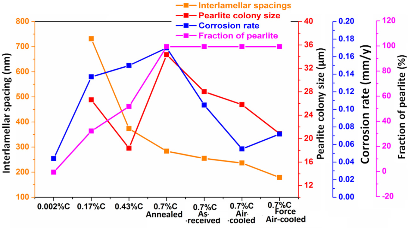
Hence, it can be expected that the entangled cementite lamellae could be broken and separated after the dissolution of ferrite lamellae in the form of small fragmented carbides. The fragmented cementite has substantially increased the interfacial area of ferrite and cementite lamellae. Consequently, the larger surface area of cementite after the dissolution of ferrite lamellae is further enhanced the cathodic activity. Therefore, a large number of micro-galvanic cells has formed and this would lead to an increase in the corrosion rate of force air-cooled pearlite steels [8].
It is important to mention that all the corroded FE-SEM images (Figures 4, 5, 6, 7, 8, 9, 10, 11, 12, 13, 14, 15) are obtained after polarization tests in 3.5% NaCl solution without etching. This is probably on account of active dissolution (as shown in Figure 3) of the ferrite phase. Moreover, the absence of passivation in 3.5% NaCl solution permits the surface to be clean from any passive oxide layer. Hence, the morphologies of the microstructures in all the specimens are visible after the polarization test. One more interesting point also noticed from FE-SEM images is that the severity of dissolution and mean depth of dissolution of ferrite lamellae decreases as the interlamellar spacing decreases since the fraction of pearlite and subsequently cementite content (Table 2) increases with an increase in carbon content. Hence, the ferrite phase has experienced rapid dissolution in the beginning. Once the dissolution of ferrite lamellae advances, the surface is covered by cementite lamellae as well as fragmented cementite plates. That cementite plates are predominantly covered the active corrosion surface. Hence, the propagation of corrosion is sluggish due to cathodically covered plate hindered reduction reaction. Coverage of the surface with cementite plates has been shown in Figures 11(b) and 12(b). This could be the reason as-received pearlite steels show a lower corrosion rate as compared to the annealed pearlite steel. Hence, the galvanic effect is predominantly more dominant when the anode-to-cathode area ratio changes. Consequently, the corrosion performance of all the steels is mainly controlled by the combined effect of interlamellar spacing, colony size, and a fraction of the pearlite. Therefore, the interfacial area of the ferrite and cementite phase has played a substantial role to alter the corrosion behaviour of all the steels.
Conclusions
The corrosion susceptibility of the 0.002%C, 0.17%C, 0.43%C and 0.70%C steels has increased greatly as the carbon content increased. The corrosion rate has increased considerably from ultra-low (0.002%) to low carbon steel (0.17%) due to the presence of pearlite in 0.17% C steel. However, the further increase in corrosion rate is obtained marginal with the increase in carbon content from low (0.17%) to medium carbon (0.43% C) and high carbon steels (0.7% C). Different fractions of pearlites and their interlamellar spacings are led to the differential corrosion within the pearlite colony in 0.17%C, 0.43%C, and 0.70%C steels. Once the fraction of pearlite has attained its maximum value (~100%), the corrosion susceptibility of the steel has further controlled by the finesse of the (interlamellar spacing) of the pearlite steels. Hence, air-cooled and force air-cooled pearlite steels have shown a lower corrosion rate as compared to the 0.17%C and 0.43%C steels since the interlamellar spacing in pearlite regions is higher in the case of 0.17%C and 0.43%C steels. On the other hand, the pearlite colony size and interlamellar spacing have decreased in the following sequence coarse (annealed) - medium (as-received) - fine (air-cooled) - very fine (force air-cooled). However, the corrosion susceptibility of high carbon pearlite steel increases in the following sequence air-cooled - forced air-cooled - as received - furnace annealed steel since variations in the finesse of the pearlite microstructure significantly alter the corrosion behaviour of pearlite steels. The normalized steel has shown the lowest corrosion rate as compared to the force normalized steel due to the entanglement of cementite stimulating the short-circuiting of the galvanic couples. However, the corrosion rate of pearlite steel decreases as the fineness of the pearlite morphology increases. Therefore, the corrosion rate of all the steels is guided by the combined effect of interlamellar spacing, colony size and fraction of pearlite,. The interfacial area of the ferrite and cementite phase has also played the crucible role to alter the corrosion susceptibility of the steels since the increase in cathodic reaction has altered the galvanic cell corrosion after the dissolution of ferrite lamellae.
