

Introduction
Finite Element Modelling
General Description
Material Models
Interaction, Boundary Conditions, and Loading
Verification of FE Modeling
Parametric Study
General Description
Effect of Outer Tube Thickness (t0)
Effect of Inner Tube Thickness (ti)
Effect of Inner Tube Diameter (Di)
Effect of Stiffening Schemes
Comparison with the Existing Code Formulas
Eurocode 4
American Specifications AISC360
Proposed Modification on the AISC360 Specifications
DBJ/T13-51-2010
Comparison of FE Results with the Predicted from Design Codes
Conclusion
Introduction
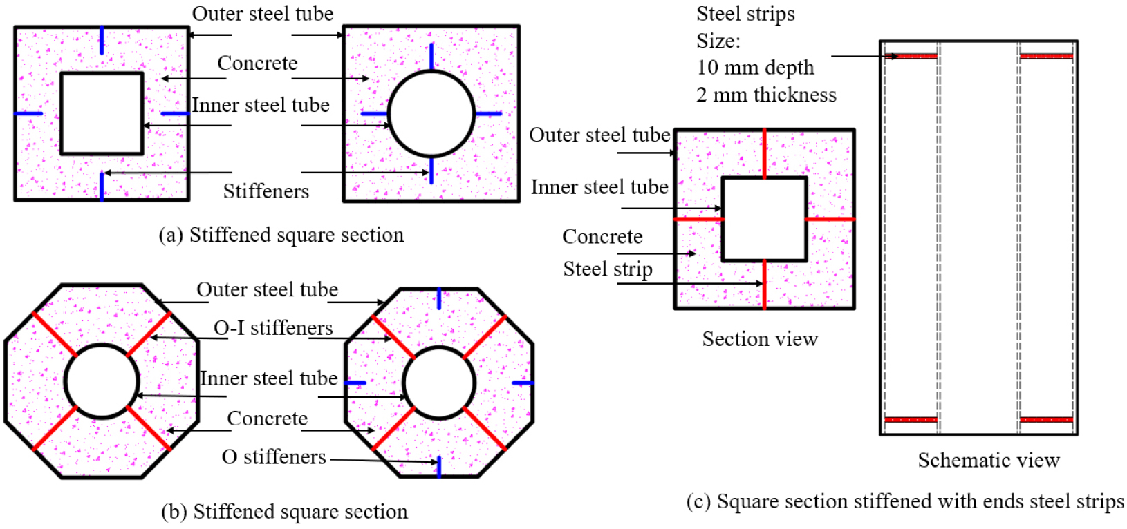
The adoption of concrete-filled steel tubes (CFSTs) in modern construction has been increasingly growing due to their excellent performance. Innovative composite members were derived from the conventional CFST members, known as concrete-filled double steel tubes (CFDSTs). CFDSTs are composite members, which consist of two concentric steel layers and sandwiched concrete in between them. They have the same characteristics as CFSTs and have less weight. The applications of CFDST columns were found to provide better structural performance over their conventional CFST counterparts in terms of load capacity, ductility, stiffness, global and local stability, and fire performance owing to the excellent interaction between their components and increased section modulus [1, 2, 3]. CFDST axial members with circular sections provide an ideal confinement effect because the confining stress in the concrete is uniform and isotropic across the section. In comparison, for the counterpart with the rectangular section, the confining stress in the concrete is non-uniform and anisotropic, which generally leads to a low increase in axial capacity. However, the former ones are mostly preferred in designing composite columns attributing to their ease of connection to the steel beams. Besides, in some studies [4, 5, 6, 7], stiffening methods/schemes have been used for enhancing the confining pressure of rectangular sections, as shown in Figure 1. Moreover, CFDST members with octagonal sections can suit the architectural and functional requirements of CFDST members because they provide greater confinement than that induced by the rectangular sections and ease of connection to the steel beam compared to circular sections. Extensive research has been performed to investigate the performance of circular [8, 9, 10, 11, 12] and square [13, 14] CFDST columns. Besides, considerable research works have been done to evaluate the behavior of OCFST columns [15, 16, 17]. However, the studies on OCFDST stub columns are still very scarce. Yang et al. [18] experimentally and numerically evaluated the performance of concrete-filled double skin steel tube (CFDSST) members with the octagonal outer tube and circular inner layer under axial compression. Yuan and Yang [19] also presented experimental and numerical investigations on the performance of concrete-filled double skin composite tube columns (CFDSCT) composed of an octagonal steel tube as its outer steel layer, a circular PVC pipe as its inner layer, and high strength concrete-filled in between them.
Owing to the limited research studies, international codes of practice such as Eurocode 4 [20], AISC 360-16 [21], and DBJ/T13-51-2010 [22] have not included design rules for such composite columns. This paper aims to carry out finite element (FE) modeling using ABAQUS software to simulate the behavior of OCFDST stub columns under axial load. The FE-generated results were therefore verified by the experimental results obtained in [6]. Moreover, the FE predicted ultimate loads were compared with the estimated ultimate strength from the current international design codes of practice.
Finite Element Modelling
General Description
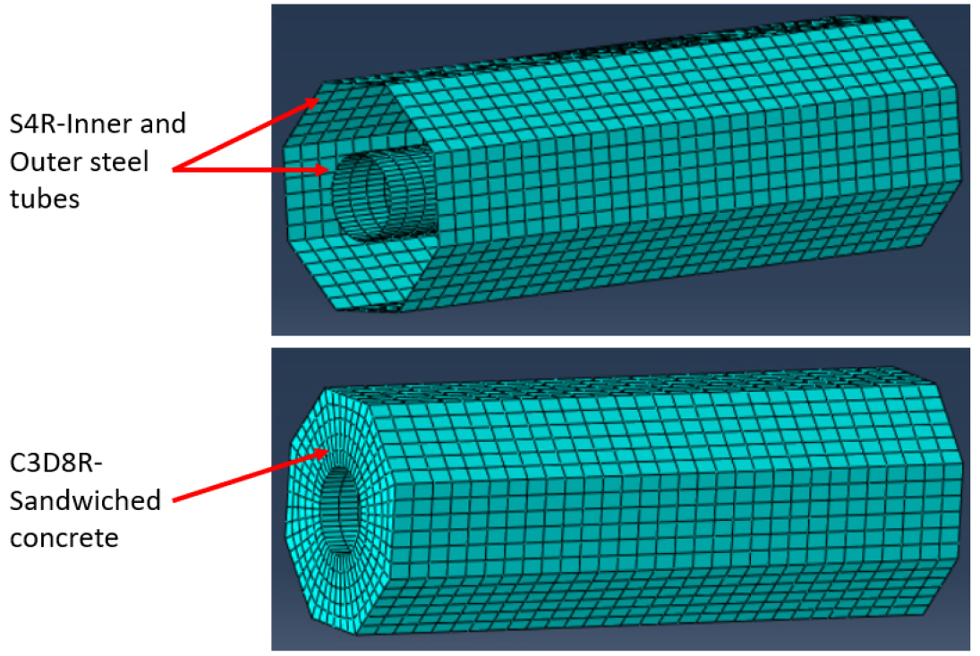
A series of three-dimensional finite element models using the ABAQUS software package has been developed. Eight-nodded solid element (C3D8R) and four-nodded shell element (SR4) with decreased integration were adopted to simulate the sandwiched concrete and the steel metals of the studied specimens, respectively. A mesh convergence study was conducted to determine the appropriate mesh type, numbers, or/and size to attain reliable simulations with a reasonable numerical model and less computational time. Considering the prediction accuracy and computational time, the convergence study indicates that a number of 25 mesh can be used in the longitudinal direction, while a number of 5 and 48 mesh can be maintained for the radial and circumferential directions of the cross-section, respectively. A sweep meshing option was utilized with a typical mesh shown in Figure 2.
Material Models
Confined Concrete Model
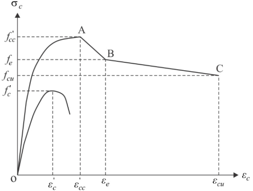
The three-stage stress-strain model depicted in Figure 3 is used to represent the behavior of the sandwiched concrete in OCFDST short columns under axial compression [23]. The ascending first part (OA) of the stress-strain curve is represented by the equation suggested by [24] for confined sandwiched concrete as expressed by Eq. (1):
where, and represent the axial stress, and the corresponding compressive strain, respectively. and denote the compressive strength of confined concrete and its corresponding confined strain, respectively. is a factor that controls the curvature and initial slope of the ascending part and calculated by Eq. (2):
where, is the concrete elastic modulus of elasticity proposed by [25] and modified by [26] to take into account the influence of column size, as given in Eq. (3):
in which, is the reduction factor taking into account the influence of the column size, proposed by [27] as given by Eq. (4):
where, designates the diameter of concrete in the CFDST stub column with octagonal or circular sections, taken as (), where represents the diameter of the outer steel tube, while denotes its thickness. The maximum confined strength () and its corresponding strain () of the concrete are calculated by the equations provided by [24] taking into account the factor given by [28] as provided in Eq. (5) and Eq. (6), respectively:
in which, () represents the confining pressure on the sandwiched concrete, and are constants provided by [29], taken as 4.1 and 20.5, respectively, and is the strain corresponds to the unconfined concrete compressive strength () determined by an equation derived by [28] as written in Eq. (7):
In this paper, the lateral confining pressure on the sandwiched concrete () in CFDST columns constructed of the octagonal section is determined by the equation provided by [30], as expressed in Eq. (8):
Two linear descending parts (AB) and (BC) of the stress-strain curve for confined concrete can be determined by the expression in Eq. (9):
Where and are compressive strains of concrete at points B and C as shown in Figure 3. The compressive strain is taken as, 10 corresponding to point B. The compressive strain at point C is taken as, 30. and are the stresses corresponding to strains and , respectively, given in Eq. (10) and Eq. (11), respectively:
where and denote the effect of confinement on the ductility of concrete in the post-peak branch, given by the equation suggested by [31], as denoted by Eq. (12) and Eq. (13), respectively:
The Drucker-Prager criterion for simulating the confined concrete in circular, elliptical, and OCFST columns [32] is adopted. The constant values of 20°, 0.8 and 30° are assumed for friction angle, flow-stress ratio, and dilation angle in defining the Drucker-Prager parameters based on sensitivity study.
Material Model for Steel Tubes
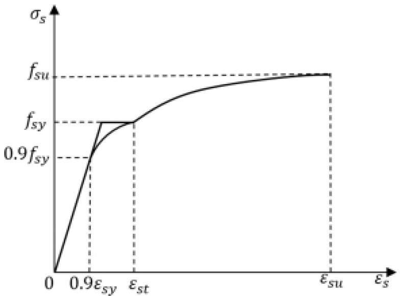
The steel tube of the axially-compressed OCFDST stub column is under bi-axial stresses attributing to the influence of steel tube confinement on the sandwich concrete. This phenomenon reduces the longitudinal yield stress of the steel tube [25, 27]. The yield stress of steel is multiplied by a factor of 0.9 to consider this effect. The equation proposed by [25] is used to predict the rounded part of the curve as shown in Eq. (14):
where describes the axial steel stress, denotes the axial steel strain, is the yield strain corresponding to the yield strength (), and is the strain at the onset of strain hardening, taken as 0.005 in this study. The stresses after the strain hardening are calculated by utilizing the equations proposed by [24], expressed in Eq. (15):
in which, represents the steel tensile strength, =0.2 is the ultimate strain and designates the steel modulus of elasticity at the onset of strain-hardening and a value of is used. The General stress-strain curve for steel is illustrated in Figure 4.
Interaction, Boundary Conditions, and Loading
Surface-to-surface interaction is utilized to model the interaction between the metal and concrete in this study [1, 5, 17]. Hard contact condition was specified to simulate the behavior in the normal direction designated by avoiding the surface penetration in compression and allowing the separation in tension [33, 34], while the Coulomb friction model with penalty friction and directionality of isotropic was adopted to simulate the interface in the tangential direction. For CFDST short columns, as the steel tubes and concrete deformed together under axial compression, it was assumed that there is little or no slip between the steel tubes and sandwiched concrete. For this reason, it was found that the behavior of CFDST stub columns is not sensitive to the friction coefficient selection between the steel and concrete [34]. Therefore, frictional coefficients of 0.25 were adopted in this study. For the longitudinal stiffeners, these components were merged with the steel tubes in a single part, hence the interaction between the steel tubes and stiffeners was considered by the inherent way of sharing common nodes. Although the longitudinal stiffeners were merged with the steel tubes, they were embedded into the sandwiched concrete [5, 33]. Since the end-stiffeners or/and clamps were not included [6], the steel and concrete are in normal contact with the stiff platens of the testing machine directly [5]. To replicate the end-friction provided by the testing machine, all three translation degrees of freedom can be restrained at all ends of the column except the displacement at the loaded end in the direction of loading. Meanwhile, the rotational degrees of freedom for both ends of the columns are not restrained which is known as pinned end-conditions. A uniformly distributed load was directly applied at the top of the specimens using a displacement control approach with a maximum displacement of 0.01 mm.
Verification of FE Modeling
The results of both developed finite element (FE) models were verified and compared against the experimental data reported in [6]. In the experimental investigation conducted by [6], a total of eight OCFDST stub columns were experimentally tested under axial compression, which is used to ensure the accuracy of the FE models. The actual slenderness ratio () that is described as the ratio of the measured side of the width of the outer octagonal steel tube () to its thickness () was 45.52 for all the test specimens. The measured slenderness ratio was kept greater than that calculated by the slenderness limit specified in ASCE 48-11 [35]. ASCE 48-11 [35] specified the limit for slenderness ratio , where is the actual yield of the stress of the outer steel tube. The details of cross-sections for the experimental specimens are summarized in Table 1. The overall comparison between FE-predicated results and test data is conducted by considering load-axial deformation () curves and ultimate design strengths. It can be observed from Figure 5 that the FE-simulated () curves are in good agreement with their experimental counterparts. Additionally, the numerically predicted ultimate strengths () are similar with those obtained from experimental tests, () as can be seen from Table 2. Table 2 provides details on material properties and overall comparison between FE-predicted and experimental ultimate strengths through considering the ratio (). It is found that the mean ratio of () is 0.97 with a corresponding standard deviation (SD) of 0.004 indicating that the adopted concrete model is capable to replicate accurately the test results of OCFDST stub columns under axial compression. Accordingly, an extensive parametric study is performed over a wide range of parameters as shown in the following sections.
Table 1.
Cross-sectional details for the experimental OCFDST stub columns
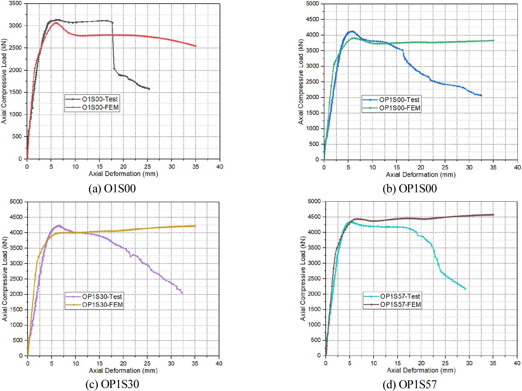
Table 2.
Material properties and overall comparison of stub columns test with FE-generated results
Parametric Study
General Description
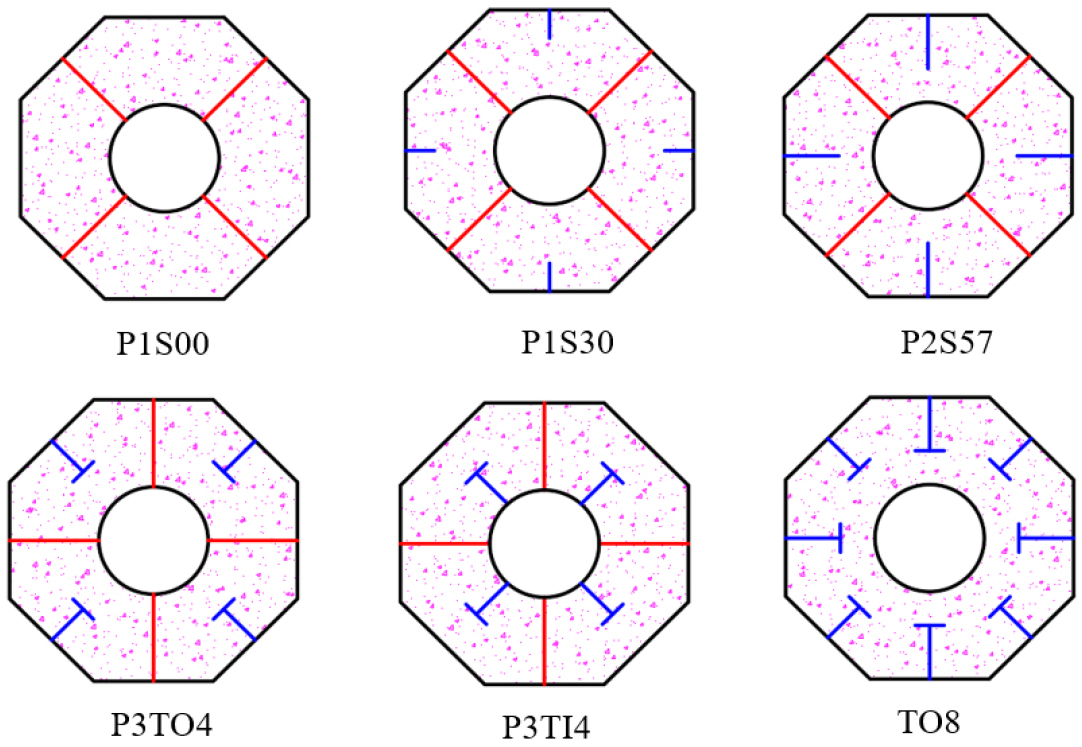
To fully understand the behavior of OCFDST columns under axial compression, there is a need to conduct further parametric analysis to cover a wider range of parameters. Possible parameters influencing the performance of these stub columns include the outer steel tube thickness (), inner steel tube thickness () and its diameter () as well as the arrangements and schemes of stiffening methods. In this study, three types of stiffening methods are selected for evaluating the effects of stiffeners arrangements and schemes on the behavior of OCFDST short columns under axial compression. The outer and inner steel tubes are welded together by a steel plate, termed as outer-inner steel tubes plate stiffeners (O-I plate stiffeners). The O stiffeners are only welded to the outer tube, while T-shaped stiffeners are welded to the outer tube are also welded to either inner or outer steel tube. Cross-sectional dimensions of the stiffeners are summarized in Table 3 with a schematic illustration of stiffening schemes shown in Figure 6.
Table 3.
Cross-sectional dimensions of stiffeners
The effects of the studied parameters are assessed in terms of load-axial deformation () curves, ultimate strength (), ultimate resistance enhancement index (RI), and ductility enhancement index (DI). The RI is known as the ratio of ultimate load of the specimens to that of the reference specimens, defined by, , in which represents the ultimate load of selected specimens and denotes the ultimate load of the reference specimens, while DI is defined as the ratio of is the ductility of the selected specimens and () to the ductility of the reference specimen [6], expressed as . The ductility of OCFDST stub columns is described as the axial-deformation at the peak load () to the axial-deformation when the load falls to 85% of the ultimate load () [3], represented by, .
Cross-sectional details and the selected specimens’ material properties for the parametric analysis are given in Table 4. New naming terms are given for parametric due to the variation in the cross-sectional properties. The OCFDST specimens were labeled to identify easily the outer and inner steel tubes thickness, the diameter of circular inner tubes, and type of stiffening schemes and their arrangement. For instance, the first letter “O” for all specimens designates the octagonal cross-section, while numbers 2, 3, 4, and 5 following symbols and represented the thickness of outer and inner tubes in . The symbol denotes the diameter of the inner tube () followed by its value in . “P”, “T”, and “S” letters refer to the O-I stiffeners, O stiffeners, and T-shaped stiffeners, respectively, while the embedded width of stiffeners are signified by numbers 1 and 2 for O stiffeners of 30 mm (width) x 2.2 mm (thickness) and 57 mm (width) x 2 mm (thickness). The numbers 4 and 8 mean that T stiffeners are welded in four and eight sides of steel tube or four segments of inner steel tube.
Table 4.
Cross-sectional details and FE-predicted results of specimens used for parametric analysis
Effect of Outer Tube Thickness (t0)
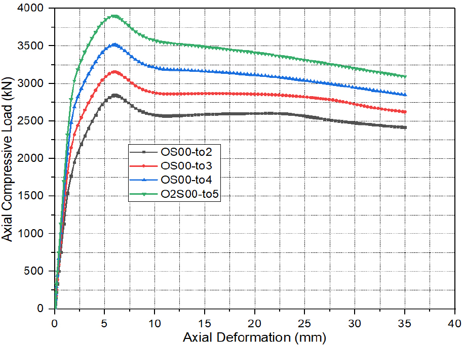
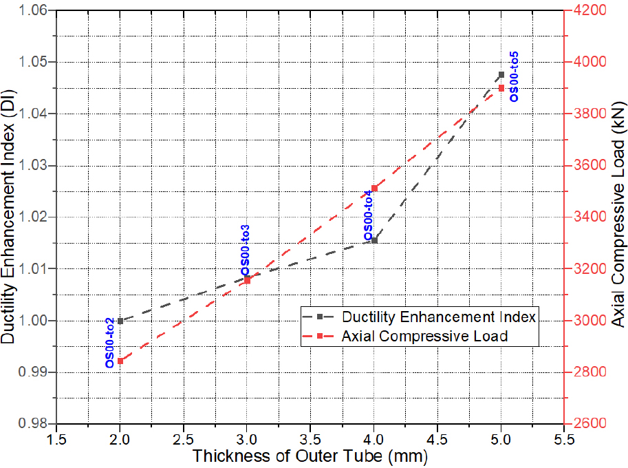
The thickness of the outer steel tube is a key parameter in controlling the performance of CFDST axial members because it affects the confinement and mode of bucking of such specimens. Figure 7 illustrates the axial load versus axial deformation () curves. It can be observed that the thickness of the outer steel tube () has no obvious effect on the initial part of the () curves. However, thickness () significantly influences the ultimate strength () of OCFDST stub columns. When the thickness () increases, the ultimate strength () greatly increases. As shown in Figure 8 that the increases with increasing the thickness () from 2 mm to 5 mm showing higher resistance enhancement index RI. It can be seen that, as compared to specimen OS00-to2, the ultimate strengths of specimens OS00-to3, OS00-to4, and OS00-to5 achieved an increment in the ultimate strength of 11, 23, and 37% as shown in Figure 8. This means that the specimens with larger outer tube thickness () can resist greater loads owing to the higher confinement effect of outer steel on the sandwich concrete in 0CFDST stub columns. Similarly, specimens of larger thickness () higher ductility enhancement indices (DIs) owning to the contribution of steel ratio () of the enlarged thickness of outer tube (), which provides higher confinement on the sandwiched concrete leading to higher ductility of the OCFDST stub columns. Overall, it can be concluded that using thicker out steel tubes can impose a higher confinement effect on the sandwiched concrete resulting in higher ultimate strength () and ductility.
Effect of Inner Tube Thickness (ti)
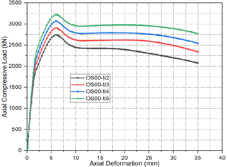
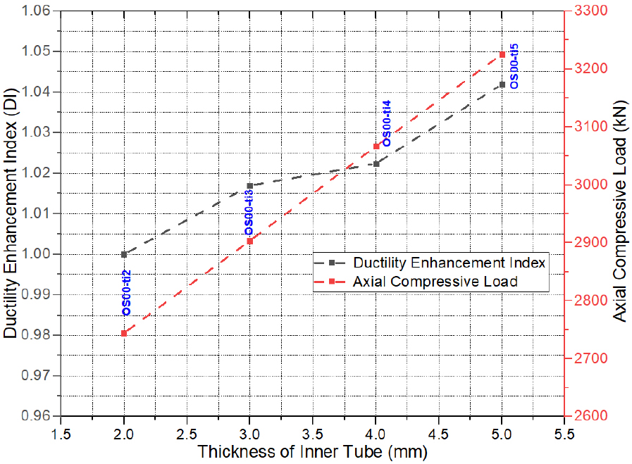
Figure 9 elucidates the effect of different thicknesses of inner steel tubes on the axial load versus axial deformation () curves. It can be seen that using a bigger thickness of the inner tube () does not the initial stiffness (elastic branch) of the () curves. However, increasing the thickness () can impose a considerable on the ultimate strength () of the OCFDST specimens. It can be observed that the specimen OS00-ti5 with thickness () of 5 mm attained the highest ultimate strength () of 3225.46 with resistance enhancement index (RI) of 1.18, as compared with the reference specimen OS00-ti2 with the smaller thickness () of 2 mm, which achieved the lowest value of 2744.19 (RI=1). Specimens OS00-ti3 (), OS00-ti4 () also attained a higher ultimate load () of 2903.67 and 3066.67 with RI values of 1.06 and 1.12, respectively. This indicates that increasing the thickness () can impose an increase of 6% in the ultimate strength () of OCFDST stub columns. As it can be observed from Figure 10 that increasing the thickness () can slightly enhance the ductility of the specimens with higher DI of 1.04% achieved for specimen OS00-ti5. Overall, it can be concluded that increasing the thickness of the inner steel tube can result in a considerable enhancement on the ultimate strength () of OCFDST stub columns with a minor ductility improvement. This could be because using thicker inner tubes does not contribute to the confinement of sandwiched concrete and only affects the strength of OCFDST stub columns rather than their ductility.
Effect of Inner Tube Diameter (Di)
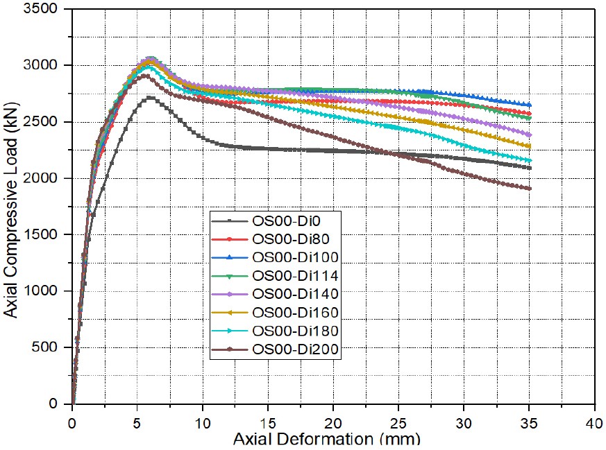
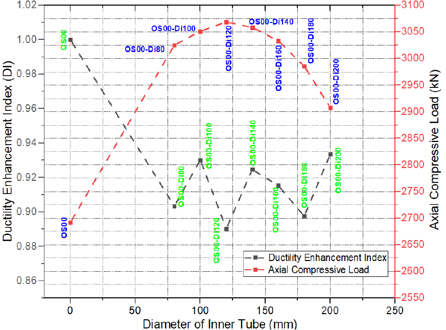
The thickness of inner steel tubes () is an essential parameter for evaluating the performance of OCFDST stub columns taking into consideration the reduction in material and weight of the axial structural members. It can be observed from Figure 11 that using the larger diameter of the inner steel tube increases the ultimate strength of OCFDST stub specimens. It can be observed from Figure 12 that as compared with other specimens, the specimens (OS00-Di120 and OS00-Di140) attain the highest ultimate load () of 3068.56 and 3058.28 , while the reference specimen (OS00) achieved the lowest ultimate strength () of 2691.66 . Besides, it can be noticed that the strengths of OCFDST stub columns significantly increase with increasing the diameter of the inner tube () up to 140 mm. However, further increases in can adversely affect the strength of OCFDST short axial members. As compared to reference specimen (OS00), it can be found that specimens with of 80, 100, 120, 140, 160, 180, and 200 mm achieved RIs values of 1.12, 1.13, 1.14, 1.14, 1.13, 1.11, and 1.08, respectively. In addition, the reference specimen showed the best ductility performance, as compared to other specimens. It can be found from Figure 12 that the DI results are scattered along with using different diameters (). This could be due to the scattered effects of the hollow ratio () and steel ratio () in affecting the ductility of OCFDST stub specimens. Overall, in order to achieve the best utilization of materials in terms of performance enhancement and weight reduction, OCFDST axial members should be designed using an appropriate diameter ().
Effect of Stiffening Schemes
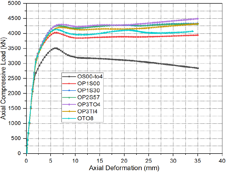
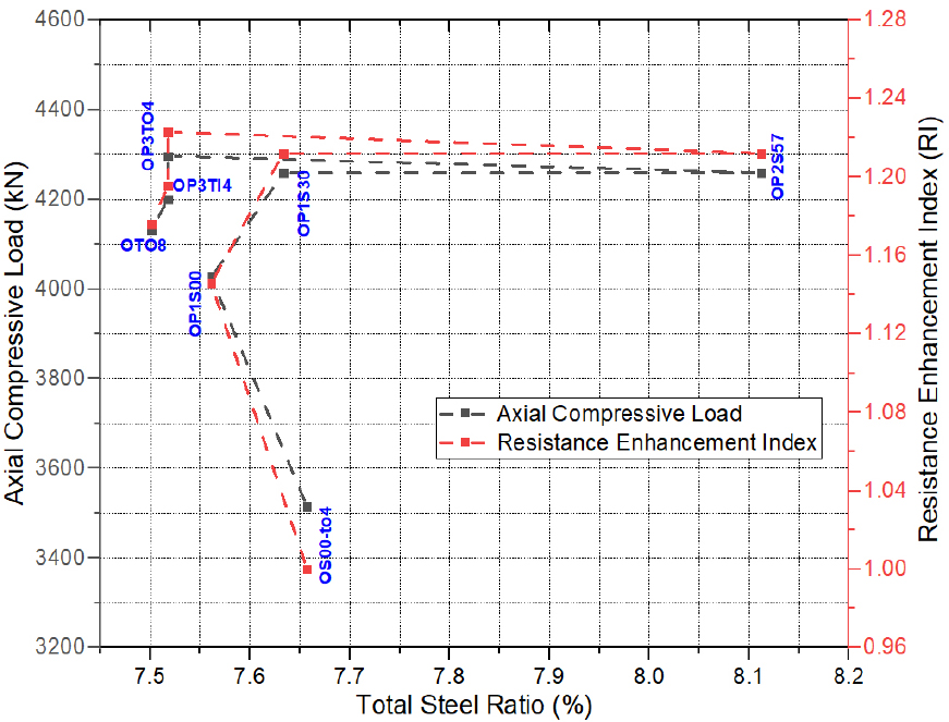
The stiffeners are used herein to compare the effects of different stiffening schemes on the mechanical behavior of stiffened OCFDST stub columns by evaluating their contribution in preventing the elastic-plastic buckling of specimens. For this proposal, the steel ratio () was nearly kept the same in the range of (7.52-7.56%) for all stiffened specimens, except for specimen (OP2S57, =8.11%). The steel ratio () for the unstiffened specimen (OS00-to4) was kept at 7.66%. It can be seen from Figure 13 that the stiffening methods have a remarkable effect on the softening branch of () curves. The softening branch shows a ductile response for all the stiffened specimens as compared with their unstiffened counterpart. Therefore, this demonstrates that strengthening OCFDST stub columns by welding steel plate stiffeners can significantly enhance the strength and ductility of these types of axial members. Additionally, as compared with the reference specimen (OS00-to4), it can be seen from Figure 14 that the specimen (OP3TO4, =7.52%). strengthening by welding four T-shaped stiffeners to the outer tube attained the highest ultimate strength () of 4296.76 with resistance enhancement index (RI) of 1.22, followed by specimens OP2S57, OP1S30, OP3TI4, OTO8, and OP1S00 with ultimate strengths () of 4259.11, 4258.65, 4200.4, 4132.18, and 4026.18 with corresponding RI values of 1.21, 1.21, 11.20, 1.18, and 1.15, respectively. This indicates that using T and O-I stiffeners increases the loads greatly. This could be because T-shaped stiffeners whether welded to outer or inner tubes increased the confinement due to the constraining effects of both O-I and T-shaped stiffeners. Therefore, the increase in the ultimate strength () is dependent on the type and arrangements of stiffening methods. In general, the use of longitudinal stiffeners could improve the strength and ductility of OCFDST stub columns. This could be mainly attributed to the improvement of the stiffness, restriction of the elastic-plastic buckling at lower loads as well as the confinement of the steel tube to the sandwiched concrete. It is concluded that the stiffeners can significantly contribute to the enhancement of strength along with achieving a reduction in the steel ratio () resulting in lower cost, light construction, and higher performance of OCFDST short columns.
Comparison with the Existing Code Formulas
Eurocode 4
The design formula for circular CFST provided in EC4 [20] is adopted to predict the design ultimate strength of the studied OCFDST stub columns. The EC4 design formula is expressed in Eq. (17):
It is worth noting that the confinement of the inner steel tube to the strength of OCFDST stub columns is not considered in Eq. (17). It is only considered as an independent term in the design equation. The slenderness dependents and are determined by Eq. (18) and Eq. (19), respectively:
Where, denotes the relative slenderness limit, as defined in EC4 [20]. The effective length factor is taken as unity herein in order to reflect the FE simulation and experimental boundary conditions. The design formula in Eq. (7) is applicable for columns with a slenderness limit of . In case the slenderness ratio exceeds this slenderness limit, an effective area () can be used for the outer steel tube, expressed by [36].
Based on the basic superposition, the enhancement factor to the sandwiched concrete in Eq. (17) was modified by [16] considering the equivalent circular section of the OCFST axial member. Hence, the modified formula in [16] is also adopted for OCFDST stub columns, expressed as:
American Specifications AISC360
The AISC360 [21] design code for concrete-filled steel composite members provided a design rule to calculate the ultimate capacity of CCFST columns under axial compression. The studied OCFDST stub columns are classified as compact, non-compact, and slender sections according to the limiting () values, as summarized in Table 5.
In this investigation, the AISC 360 design formula is adopted for the studied specimens with compact, non-compact and slender sections. The compact section has a slenderness limit of , which can approach the yield strength of steel tubes and exhibit a concrete compressive strength of 0.95 due the to higher confinement effect induced by the outer steel tube. The non-compact section has a slenderness limit of , which can also attain the yield strength of steel tube and develop a concrete compressive strength between 0.95 and 0.7 due to less confinement than that of compact section due to local buckling [7, 37]. A slender section has a slenderness limit of and can neither reach the yield strength nor confine the concrete beyond 0.7 [7, 38]. The design formula provided by AISC360 [21] is expressed as
where, is the slenderness of the equivalent circular section of the outer octagon steel tube. is the elastic critical buckling stress of outer octagonal steel tube, determined from Eq. (23), while and are calculated by Eq. (24) and Eq. (25), respectively.
Proposed Modification on the AISC360 Specifications
The compressive cross-sectional resistance provided by AISC360 can be modified herein for OCFDST stub columns considering the limit of provided in ASCE 48-11 [35] for the octagonal section, as shown in Table 6.
Table 6.
Limiting () in composite members under axial compression [35]
| Code | Compact | Non-compact | Slender |
| ASCE/SEI 48 |
DBJ/T13-51-2010
The design formula given by DBJ/T13-51-2010 [22] for circular CFST columns is also used to determine the axial capacities of the studied specimens, which are expressed by:
Comparison of FE Results with the Predicted from Design Codes
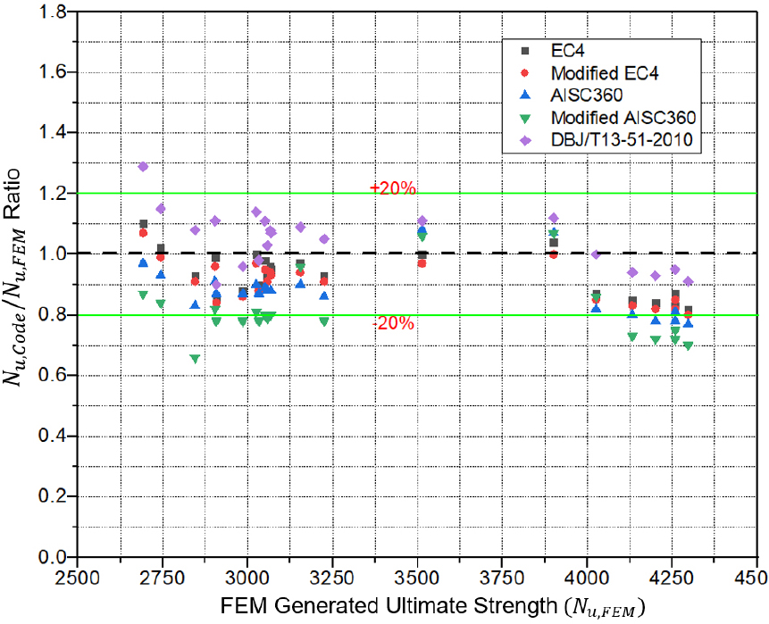
According to the authors’ best knowledge, there are no existing compressive design strength formulas for calculating the ultimate design strength of OCFDST stub columns. The FE results of such axial members are compared with the design strength predictions determined using the provisions of Eurocode 4 [20], modified EC4 [16], AISC360-16 [21], modified AISC360 and DBJ/T13-51-2010 [22], as summarized in Table 7. The comparison is also graphically illustrated in Figure 15, where the ratio of the calculated ultimate loads-to-the FE predicted ultimate strengths () has been plotted against the FE-predicted ultimate strengths (). It can be seen that both EC4 [20] and modified EC4 [16] formula can accurately estimate the ultimate strength of OCFDST stub columns with wide variation of parameters with better prediction provided by the original EC4 formula. However, these provisions slightly provide conservative predictions of ultimate strength for specimens with different stiffening schemes. Similarly, the code, AISC360 and modified AISC360 significantly also give safe predictions for non-stiffened specimens and greatly underestimates the ultimate loads of stiffened specimens, while it slightly underestimates the capacities of specimens with different types and arrangements of stiffeners. DBJ formula yields more un-conservative predictions of ultimate strengths for the unstiffened specimens with varying outer tube thickness, thickness, and diameter of the inner tube. DBJ equation greatly overestimates the ultimate strength of OS00 (CFST stub column). However, DBJ provisions give accurate results of the OCFDST stub columns with different stiffening schemes. As given in Table 7, it can be seen that the mean ratios () for EC4, modified EC4, modified AISC360, and DBJ formula are 0.93, 0.91, 0.88, 0.81, and 1.04 with corresponding standard deviation (SD) values of 0.073, 0.069, 0.079, 0.1, and 0.096, respectively. This confirms that EC4 and modified EC4 formulas can safely be used to predict the design ultimate strength of OCFDST stub columns. AISC360 can also give a reasonable for non-stiffened specimens while, DBJ provides un-conservative predictions of ultimate strength when applied to non-stiffened OCFDST stub columns, while it can accurately predict the ultimate strength of the OCFDST axial members with different stiffening schemes. Overall, it can be confirmed that all design codes except DBJ can safely predict the strength of un-stiffened specimens and underestimate the strength of specimens with different stiffening schemes. This could be because the contribution of stiffeners was considered as an additional term of () in the calculation of the ultimate strength. Hence, the contribution of welded stiffeners and arrangement to the confinement of steel tubes were not considered by the design codes.
Table 7.
Overall comparison of the FE results with predictions from design codes
| Column Label | FEM | EC4 [20] | Modified EC4 [16] | AISC360 [21] | Modified AISC360 | DBJ [22] | |||||
(kN) | (kN) | (kN) | (kN) | (kN) | (kN) | ||||||
| OS00-to2 | 2845.28 | 2647.30 | 0.93 | 2594.74 | 0.91 | 2350.70 | 0.83 | 1890.89 | 0.66 | 3067.37 | 1.08 |
| OS00-to3 | 3155.35 | 3056.10 | 0.97 | 2978.50 | 0.94 | 2847.70 | 0.90 | 3019.19 | 0.96 | 3430.80 | 1.09 |
| OS00-to4 | 3513.88 | 3524.13 | 1.00 | 3422.30 | 0.97 | 3787.42 | 1.08 | 3738.16 | 1.06 | 3894.59 | 1.11 |
| OS00-to5 | 3901.24 | 4042.73 | 1.04 | 3917.48 | 1.00 | 4164.07 | 1.07 | 4164.07 | 1.07 | 4368.02 | 1.12 |
| OS00-ti2 | 2744.19 | 2785.70 | 1.02 | 2714.79 | 0.99 | 2557.41 | 0.93 | 2294.50 | 0.84 | 3154.77 | 1.15 |
| OS00-ti3 | 2903.67 | 2862.91 | 0.99 | 2792.00 | 0.96 | 2633.96 | 0.91 | 2371.05 | 0.82 | 3231.32 | 1.11 |
| OS00-ti4 | 3066.67 | 2939.42 | 0.96 | 2868.51 | 0.94 | 2709.82 | 0.88 | 2446.92 | 0.80 | 3307.19 | 1.08 |
| OS00-ti5 | 3225.46 | 3015.23 | 0.93 | 2944.32 | 0.91 | 2785.00 | 0.86 | 2522.09 | 0.78 | 3382.37 | 1.05 |
| OS00 | 2691.66 | 2960.75 | 1.10 | 2878.10 | 1.07 | 2600.66 | 0.97 | 2337.75 | 0.87 | 3475.39 | 1.29 |
| OS00-Di100 | 3024.88 | 3014.05 | 1.00 | 2937.18 | 0.97 | 2717.15 | 0.90 | 2454.25 | 0.81 | 3455.30 | 1.14 |
| OS00-Di100 | 3051.15 | 2977.43 | 0.98 | 2903.81 | 0.95 | 2717.12 | 0.89 | 2454.21 | 0.80 | 3378.42 | 1.11 |
| OS00-Di120 | 3068.56 | 2920.00 | 0.95 | 2850.36 | 0.93 | 2704.86 | 0.88 | 2441.96 | 0.80 | 3272.27 | 1.07 |
| OS00-Di140 | 3058.28 | 2841.69 | 0.93 | 2776.75 | 0.91 | 2680.40 | 0.88 | 2417.49 | 0.79 | 3136.82 | 1.03 |
| OS00-Di160 | 3033.15 | 2742.55 | 0.90 | 2683.02 | 0.88 | 2643.72 | 0.87 | 2380.81 | 0.78 | 2972.08 | 0.98 |
| OS00-Di180 | 2985.6 | 2622.74 | 0.88 | 2569.36 | 0.86 | 2594.82 | 0.87 | 2331.92 | 0.78 | 2861.73 | 0.96 |
| OS00-Di200 | 2907.42 | 2482.52 | 0.85 | 2436.00 | 0.84 | 2533.71 | 0.87 | 2270.81 | 0.78 | 2628.25 | 0.90 |
| OP1S00 | 4026.18 | 3517.72 | 0.87 | 3440.13 | 0.85 | 3309.33 | 0.82 | 3480.82 | 0.86 | 4006.57 | 1.00 |
| OP1S30 | 4258.65 | 3554.46 | 0.83 | 3483.55 | 0.82 | 3324.86 | 0.78 | 3061.96 | 0.72 | 4031.86 | 0.95 |
| OP2S57 | 4259.11 | 3692.54 | 0.87 | 3621.62 | 0.85 | 3462.94 | 0.81 | 3200.03 | 0.75 | 4060.30 | 0.95 |
| OP3TO4 | 4296.76 | 3521.13 | 0.82 | 3450.21 | 0.80 | 3291.53 | 0.77 | 3028.62 | 0.70 | 3888.89 | 0.91 |
| OP3TI4 | 4200.4 | 3521.13 | 0.84 | 3450.21 | 0.82 | 3291.53 | 0.78 | 3028.62 | 0.72 | 3888.89 | 0.93 |
| OTO8 | 4132.18 | 3516.37 | 0.85 | 3445.46 | 0.83 | 3286.77 | 0.80 | 3023.86 | 0.73 | 3884.13 | 0.94 |
| Mean | 0.93 | 0.91 | 0.88 | 0.81 | 1.04 | ||||||
| Standard Deviation (SD) | 0.073 | 0.069 | 0.079 | 0.100 | 0.096 | ||||||
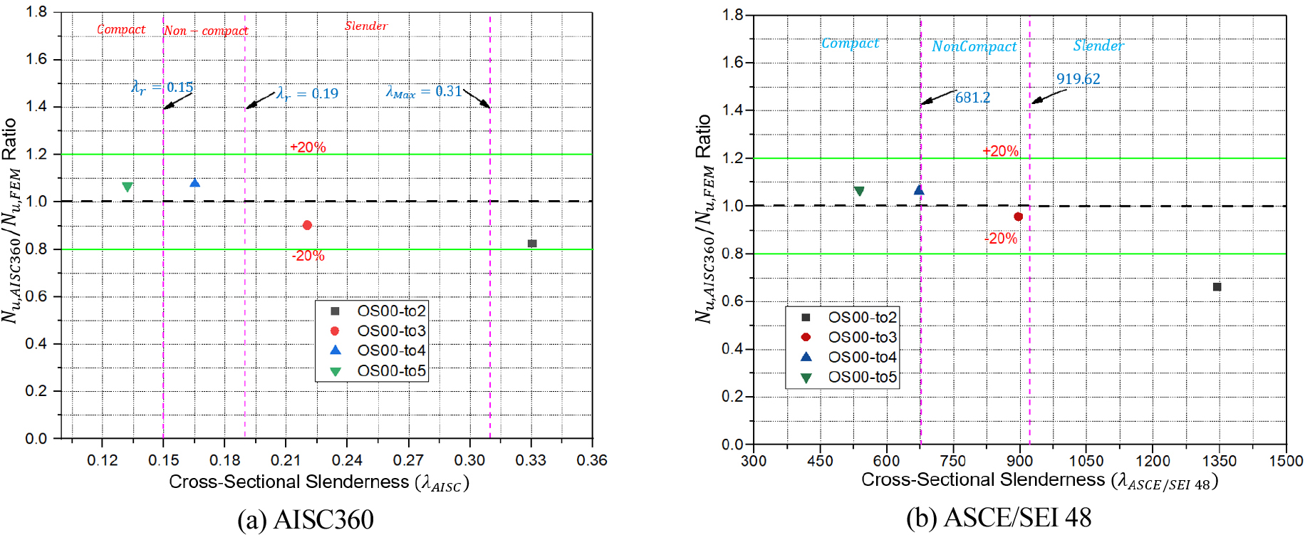
The accuracy of AISC360 and modified AISC360 is further assessed by comparing the FE results with their design strength formula provisions considering the provided cross sectional slenderness range, as shown in Figure 16, in which the ratios of FE results to the strength predictions from design formulas are plotted against the cross-sectional slenderness and provided by AISC360 and ASCE 48-11 [35], respectively. It can be seen from Figure 16 that both AISC360 and modified AISC360 provide safe predictions of ultimate strengths of OCFDST stub columns with compact and non-compact sections. AISC360 yields very conservative predictions of ultimate strength of the slender section, while modified AISC360 significantly underestimates the strength of slender section.
Conclusion
The current paper provides an extensive evaluation of OCFDST stub columns to address their behavior under axial compression and the following conclusions can be drawn:
a)The numerically generated axial load-deformation () curves show a well agreement with those obtained from tests. Ultimate loads obtained from numerical simulations are closed with those of experiment with a mean ratio of () of 0.97 and corresponding standard deviation (SD) of 0.004. Therefore, a subsequent parametric study was conducted in order to investigate the effects of different parameters including the thickness of the outer steel tube (), thickness of inner steel tube (), the diameter of inner steel tube () and type and arrangement of stiffening schemes.
b)It was found that using thicker out steel tubes can impose a higher confinement effect on the sandwiched concrete resulting in higher ultimate strength () and ductility.
c)It was also noticed that enlarging the thickness of the inner steel tube () can result in a considerable enhancement on the ultimate strength () of OCFDST stub columns with a minor ductility improvement. This could be because using thicker inner tube does not contribute to the confinement of sandwiched concrete and only affects the strength of OCFDST stub columns rather than their ductility.
d)In addition, it can be observed that the strengths of OCFDST stub columns significantly increase with increasing the diameter of inner tube () up to 140 mm. However, further increase in can adversely affect the strength of OCFDST short axial members.
e)Besides, it was observed that the stiffeners can significantly contribute to the enhancement of strength with achieving a reduction in the steel ratio () resulting in the achievement of lower cost, light construction, and higher performance of OCFDST short columns.
f)Both EC4 and modified EC4 formulas yield the most accurate predictions of ultimate loads for non-stiffened specimen, while. AISC360 and modified can also give a reasonable for non-stiffened specimens. However, DBJ provides un-conservative predictions when applied to OCFDST stub columns. It was also observed that all design codes except DBJ, underestimate the capacities of stiffened specimens with slender sections.
It can be concluded that the developed FE model in this study provides the benchmark numerical results for the design of OCFDST stub columns. Further experimental program on OCFDST columns with high and ultra-high-strength concretes and high-strength steel is required.
